
Mechanism of stacking fault annihilation in 3C-SiC epitaxially grown on Si(001) by molecular dynamics simulations
Andrey
Sarikov
 *ab,
Anna
Marzegalli
c,
Luca
Barbisan
a,
Massimo
Zimbone
d,
Corrado
Bongiorno
e,
Marco
Mauceri
f,
Danilo
Crippa
g,
Francesco
La Via
e and
Leo
Miglio
a
*ab,
Anna
Marzegalli
c,
Luca
Barbisan
a,
Massimo
Zimbone
d,
Corrado
Bongiorno
e,
Marco
Mauceri
f,
Danilo
Crippa
g,
Francesco
La Via
e and
Leo
Miglio
a
aL-NESS and Department of Materials Science, University of Milano-Bicocca, via R. Cozzi 55, 20125 Milan, Italy
bV. Lashkarev Institute of Semiconductor Physics NAS Ukraine, 45 Nauki Avenue, 03028 Kyiv, Ukraine. E-mail: sarikov@isp.kiev.ua
cL-NESS and Department of Physics, Politecnico di Milano, via Anzani 42, 22100 Como, Italy
dIMM-CNR, via S. Sofia 24, 95128 Catania, Italy
eIMM-CNR, VIII Strada 5, 95121 Catania, Italy
fLPE, Sedicesima Strada, Zona Industriale, Blocco Torre Allegra, 95121 Catania, Italy
gLPE S.p.A, via Falzarego 8, 20021 Baranzate, Italy
First published on 4th January 2021
Abstract
In this work, the annihilation mechanism of stacking faults (SFs) in epitaxial 3C-SiC layers grown on Si(001) substrates is studied by molecular dynamics (MD) simulations. The evolution of SFs located in the crossing (![[1 with combining macron]](https://www.rsc.org/images/entities/char_0031_0304.gif) 11) and (11) glide planes is considered. This evolution is determined by the interaction of 30° leading partial dislocations (PDs) limiting the stacking faults under the slightly compressive (∼0.45%) strain condition during the 3C-SiC layer growth. It is characterized in key terms: the distance between the PDs and the mutual orientation of their Burgers vectors. Two SF annihilation scenarios are revealed. In the first scenario, two PDs with opposite screw components of Burgers vectors, leading the SFs located in the (11) and (11) planes, are close enough (∼15 nm or less) and attract each other. As a result, the propagation of both SFs is suppressed via the formation of a Lomer–Cottrell lock at their intersection. In the second scenario, two PDs are far away one from the other (beyond ∼15 nm) and do not interact, or they repulse each other having equal screw components of their Burgers vectors. In this case, the propagation of only one of the SFs is suppressed. Obtained results explain the mechanism of SF annihilation and formation of SF intersection patterns experimentally observed by TEM investigations. They will provide important implications for the elaboration of advanced methods for the reduction of SF concentrations in epitaxial 3C-SiC layers on Si substrates.
11) and (11) glide planes is considered. This evolution is determined by the interaction of 30° leading partial dislocations (PDs) limiting the stacking faults under the slightly compressive (∼0.45%) strain condition during the 3C-SiC layer growth. It is characterized in key terms: the distance between the PDs and the mutual orientation of their Burgers vectors. Two SF annihilation scenarios are revealed. In the first scenario, two PDs with opposite screw components of Burgers vectors, leading the SFs located in the (11) and (11) planes, are close enough (∼15 nm or less) and attract each other. As a result, the propagation of both SFs is suppressed via the formation of a Lomer–Cottrell lock at their intersection. In the second scenario, two PDs are far away one from the other (beyond ∼15 nm) and do not interact, or they repulse each other having equal screw components of their Burgers vectors. In this case, the propagation of only one of the SFs is suppressed. Obtained results explain the mechanism of SF annihilation and formation of SF intersection patterns experimentally observed by TEM investigations. They will provide important implications for the elaboration of advanced methods for the reduction of SF concentrations in epitaxial 3C-SiC layers on Si substrates.
Introduction
Cubic silicon carbide (3C-SiC) layers epitaxially grown on Si(001) substrates are promising for the manufacture of high power and high frequency electronic devices.1–5 However, such layers abound in extended defects mostly resulting from about 19.7% lattice mismatch between the dissimilar epi-layer and substrate materials.6 Stacking faults (SFs) belong to the most important ones dominating over entire 3C-SiC layer thickness and causing degradation of electrical performance7 by the accumulation of dopants8 or due to recombination levels introduced by SF terminating partial dislocation (PD) complexes.9 Unlike other types of extended defects, stacking faults cannot be completely eliminated by mutual annihilation even in very thick 3C-SiC layers due to concurrent SF generation.10–12 The minimum SF densities achieved so far for 3C-SiC grown on flat Si(001) substrates amount to about 104 cm−1.13 Specific substrate patterning such as undulation,14,15 inverted pyramidal structuring16,17 and deep profiling in the form of ridges or pillars18,19 was proposed to reduce this value. Nevertheless, 3C-SiC layers with acceptably lower SF concentrations still remain a challenging goal.SF elimination may take place by mutual annihilation mechanism,10,20i.e. the propagation of stacking faults lying in opposite {111} planes is suppressed upon their intersection. This suppression is achieved by a formation of a Lomer–Cottrell lock by two Shockley partial dislocations that lead the SFs or by locking of gliding of an SF leading PD upon encountering the crossing stacking fault.13,21 This mechanism requires a deeper comprehension in terms of the conditions of 3C-SiC epi-layer growth as well as the characteristics of stacking faults and terminating them partial dislocations.
In this work, we use molecular dynamics (MD) simulations to determine the main factors governing the suppression of SF propagation and the formation of SF intersection patterns in 3C-SiC layers grown on Si(001) substrates. Based on the obtained results, we characterize the SF annihilation mechanism in key terms: stress in the 3C-SiC layers at different growth stages as well as mutual arrangement and orientations of the Burgers vectors of SF leading partial dislocations.
Methods
3C-SiC layers were grown hetero-epitaxially on 4-inch 650 μm-thick Si(001) substrates using chemical vapor deposition in a horizontal hot-wall reactor. Prior to layer growth, Si substrates underwent etching and carbonization step performed at 1100 °C by introducing H2 and H2 plus ethylene (C2H4) for the former and the latter process, respectively. Following carbonization, the temperature was ramped up to 1370 °C and growth took place at 104 Pa at a C/Si ratio of 0.8. The gases used during the growth were trichlorosilane and ethylene as silicon and carbon precursors, respectively, and H2 as a carrier gas. The final 3C-SiC thickness was 30 μm. The defect structure was analyzed using high-angle annular dark field scanning transmission electron microscopy (HAAD-STEM) carried out on a JEOL 2010F microscope. The studied samples were slightly tilted (1–2°) in the (002) direction, which enabled higher contrast of SF visualization.MD simulations were performed by using the Large-scale Atomic/Molecular Massively Parallel Simulator (LAMMPS)22 in the canonical ensemble (NVT) using a Nose–Hoover thermostat regime. The atom interactions in the 3C-SiC phase were described by the Vashishta potential.23 This potential reliably predicts the evolution of extended defects in 3C-SiC and provides non-zero stacking fault energy by taking into account atom interactions beyond the first coordination sphere.24 The analyses of defect configurations obtained at various time steps were performed using the Open Visualization Tool (OVITO) software.25
The simulation cell was set as an orthogonal box defined by the vectors [10], [110] and [001] in the direction X, Y and Z, respectively. The dimensions of the box with 86![[thin space (1/6-em)]](https://www.rsc.org/images/entities/char_2009.gif) 400 atoms, 281.6 × 12.4 × 240.2 Å3, ensured an optimum balance between the computational cost and the accuracy of the description of considered defects. Periodic boundary conditions were applied in the X and Y directions to model the infinite 3C-SiC slab, while the free surface condition was set in the Z direction. Moreover, bottom atomic rows were fixed during the simulations to model the effect of a thick Si substrate on the 3C-SiC epi-layer.21
400 atoms, 281.6 × 12.4 × 240.2 Å3, ensured an optimum balance between the computational cost and the accuracy of the description of considered defects. Periodic boundary conditions were applied in the X and Y directions to model the infinite 3C-SiC slab, while the free surface condition was set in the Z direction. Moreover, bottom atomic rows were fixed during the simulations to model the effect of a thick Si substrate on the 3C-SiC epi-layer.21
Stacking faults were formed in the simulation cell by inserting pairs of Shockley partial dislocations limiting them. PDs were inserted parallel to the Y axis by shifting all the simulation cell atoms by the displacement vectors calculated in the framework of dislocation theory26 and additionally corrected to account for the infinite dislocation arrays created by the periodic boundary condition along the X axis.9,26,27
MD simulations were performed with the time step of 0.3 fs at the thermostat temperature of 1800 K. Thermal dilation of the 3C-SiC layer corresponding to this temperature was accounted for scaling up the cell dimensions by the factor obtained from the 3C-SiC bulk cell simulations in the NPT ensemble using the Nose–Hoover barostat regime.
Results and discussion
Fig. 1 shows a low-magnification cross-section TEM image of the epitaxial 3C-SiC layer observed in the (110) projection plane. This image is taken at a distance exceeding 1 μm from the 3C-SiC/Si substrate interface such that the SF density is sufficiently low and isolated SF intersections can be observed.11 The SFs lying in the (11) and (11) glide planes and extending in the direction bottom-top of the 3C-SiC layer are individuated as the white lines tilted by about 35° with respect to the layer growth direction [001]. Upon the intersection, these stacking faults form “inverted V” or “λ” patterns corresponding to complete or partial SF annihilation, respectively. Note that other SF intersections may be observed in the 3C-SiC epi-layers related to SF generation, which are not considered in this study.
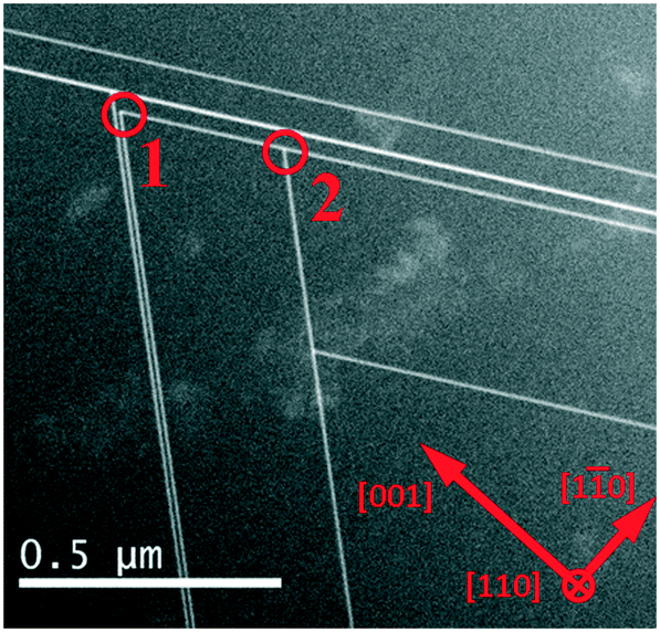 | ||
| Fig. 1 Low-magnification TEM image of the 3C-SiC layer epitaxially grown on Si(001) substrate. [001] is the growth direction. Stacking faults appear as the white lines. Marked areas 1 and 2 show the “inverted V” and “λ”-shaped stacking fault intersections. | ||
The stacking faults shown in Fig. 1 may contain various numbers of faulted atomic lattice planes. Their evolution, however, is determined by the intrinsic stacking faults composing them, i.e. the SFs consisting of only one faulted plane.28
We consider the evolution of intrinsic SFs as a result of the motion of Shockley partial dislocations terminating them due to the stress in 3C-SiC at different stages of layer growth. The carbonization step prior to the 3C-SiC deposition is intended to convert the upper part of a Si substrate into a thin 3C-SiC film with the accommodation of the lattice mismatch between these two materials.10,13 At this stage, the major part of the misfit tensile strain resulted from about 4:5 ratio of the 3C-SiC and Si lattice constants is released by the formation of Lomer dislocations on every five 3C-SiC planes on an average at the 3C-SiC/Si substrate interface.29 Such interface structuring, however, is still insufficient to accommodate all the tensile strain in the 3C-SiC film as may be inferred from the temperature dependences of the 3C-SiC and Si lattice constants.30,31 Additional strain is released by the generation of perfect glide dislocations with the Burgers vectors 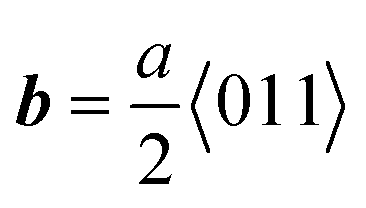 , which dissociate into Shockley partial pairs with
 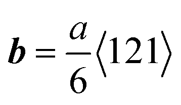 , forming the angles 30° and 90° with their dislocation lines, separated by stacking faults as a result of dislocation energy minimization.32 Under tensile strain condition during carbonization step, the leading 90° PDs are driven toward the 3C-SiC/Si interface and are anchored there, while the trailing 30° ones remain closer to the 3C-SiC layer surface leaving numerous stacking faults, extending in the 3C-SiC bulk layer observed experimentally.21
Raising the temperature during the 3C-SiC deposition after carbonization turns the relaxed 3C-SiC layer to a slightly compressive strain condition (about 0.45%) as follows from the temperature dependences of the 3C-SiC and Si lattice constants.30,31 Relaxation of compressive strain is led by 30° partials,33 which should be expelled toward the free 3C-SiC surface leaving extending stacking faults behind. Interaction of gliding in opposite {111} planes (such as (11) and (11)) 30° PDs each with other or with crossing SFs should lead to the formation of the “inverted V” or “λ” intersection patterns of stacking faults and to the suppression of propagation of the latter observed experimentally.
Molecular dynamics simulations are an efficient tool to study the dynamics of the processes that cannot be explicitly observed experimentally, including the motion and interaction of partial dislocations. However, because of the use of empirical potentials fitted for limited sets of material characteristics, MD simulations cannot be regarded as universally applied or quantitatively precise. The choice of the most suitable potential for a particular task is often required. In our previous publication,24 we have validated the reliability of the dislocation dynamics in 3C-SiC layers with Vashishta potential. Therefore, we treat the results on the mechanisms of dislocation motion and interaction, obtained in this work, with high confidence. At the same time, however, the numerical values characterizing the processes under study remain potential-dependent and may deviate to some extent from the respective real values.
To simulate the SF evolution resulting from the gliding and interaction of leading 30° partial dislocations under compressive strain condition, pairs of Shockley partials, each pair consisting of 30° and 90° PDs, were inserted in the glide set of the (11) and (11) planes of the simulation cell. The 90° partials were placed close to the cell bottom in the region of immobile atoms to model their experimentally observed trapped state at the 3C-SiC/Si substrate interface during the 3C-SiC layer growth.21 The 30° partials separated from their 90° counterparts by stacking faults, were placed in the 3C-SiC bulk at various distances from the simulation cell bottom to model various mutual arrangements of SFs and leading PDs. The dimensions of the cell were scaled so to ensure compressive strain in the X and Y directions at the simulation temperature. In our MD simulations, the average compressive strain of 1.2% instead of the experimental value of ∼0.45% was applied. It was recalculated so to ensure a proper balance between the Peach–Koehler force acting on the leading dislocations, and the increased attractive force within the 30–90° partial pairs due to the SF energy overestimation by the Vashishta potential (12.09 meV Å−2 (ref. 24) vs. 2.51 meV Å−2 obtained by DFT calculations34).
Fig. 2 depicts the MD simulation results on the formation of an “inverted V” intersection pattern, in which the annihilation of both participating SFs is apparent. In this case, two 30° SF leading PDs with opposite screw components of Burgers vectors interact attractively according to the reaction: 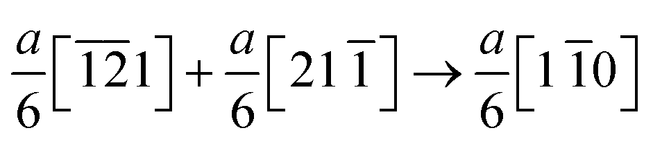 (or, alternatively,
  ). Dislocation attraction takes an effect at the distances not exceeding the interaction radius equal to approximately 15 nm, according to our MD simulations. As noted above, although MD simulations unambiguously point to the existence of the maximum radius for dislocation interaction, its value should be regarded as potential-dependent and subject to some deviation from the real value. The resulting stable dislocation complex formed at the SF intersection is the Lomer–Cottrell lock dislocation evidenced by a six-member ring of atoms (see Fig. 2c) as reported in ref. 21.
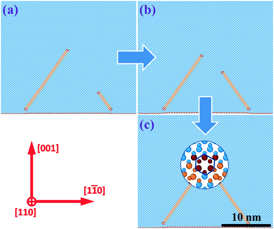 | ||
| Fig. 2 MD simulation snapshots of the formation of “inverted V”-shaped intersection of stacking faults in 3C-SiC epi-layers on a Si(001) substrate by the interaction of leading 30° partial dislocations with opposite screw components of Burgers vectors. The simulation time: a – 0, b – 120 ps, and c – 180 ps. Blue atoms correspond to the Si and C atoms in the cubic diamond lattice, orange atoms belong to the stacking faults. Inset in panel (c) shows the atomic configuration of the formed Lomer–Cottrell lock dislocation. | ||
Fig. 3 shows two pathways of the formation of “λ”-type SF intersections. In the first case shown in panels (a) to (c), the SF leading partial dislocations do not interact efficiently and propagate independently because of the distance between them exceeding the interaction radius. The “rear” PD gliding in the (11) plane, stops upon encountering the stacking fault left behind by the “advanced” PD in the (11) plane. In view of the independence of the motion of both dislocations, the relation between their Burgers vectors is not important: the exclusion of one SF from further propagation is the same for both equal and opposite orientations of the screw components of the dislocation Burgers vectors. The atomic configuration of the SF intersection is shown in the inset of Fig. 3c.
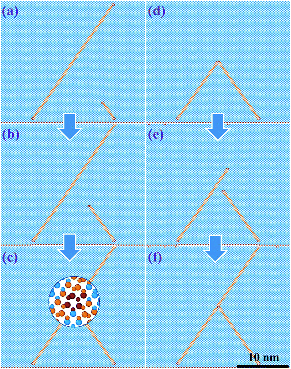 | ||
| Fig. 3 MD simulation snapshots of the formation of “λ”-shaped intersections of stacking faults in 3C-SiC epi-layers on a Si(001) substrate in the case of the large distance between the 30° leading dislocations (a–c) and as a result of the interaction of closely spaced 30° dislocations with equal screw components of Burgers vectors (d–f). Simulation time: a – 0, b – 360 ps, c – 540 ps, and d – 0, e – 60 ps, f – 200 ps. Blue atoms correspond to the Si and C atoms in the cubic diamond lattice, orange atoms belong to the stacking faults. Inset in panel (c) shows the atomic configuration of the intersection of 30° partial dislocation with crossing stacking fault, also corresponding to the intersection in panel (f). | ||
An alternative pathway for the formation of the “λ”-shaped SF intersection is presented in the panels (d) to (f) of Fig. 3. In this case, closely spaced (within the interaction radius) 30° PDs with equal screw components of their Burgers vectors repulse each other. For better illustration of repulsion and impossibility to maintain a stable complex together, dislocations were initially placed at the same point in Fig. 3d. As a result, one PD advances (in our case, the one lying in the (11) plane) leaving a stacking fault behind, while the other one (in the (11) plane) encounters it and stops from further gliding. The atomic configuration of the intersection junction coincides with the one presented in the inset of Fig. 3c.
Results of MD simulations demonstrate that the formation of SF intersection patterns in 3C-SiC layers is determined by the gliding of 30° partial dislocations terminating the SFs. This gliding takes place under the action of three forces, two of them driving the 30° PDs toward the free 3C-SiC layer surface and the rest one holding them back.26 The former are represented by the image force, attracting the dislocations to the free surface independently on the Burgers vector orientations, and the Peach–Koehler force, which acts on the 30° partials under consideration in the upward direction to release the compressive strain in the 3C-SiC layers induced by the deposition process. The third force originates from the tendency to decrease the positive energy of stacking faults formed within the 30–90° dislocation pairs; it attracts 30° and 90° partials toward each other and hence hinders the 30° partial forward gliding. As a result, 30° PDs tend to be expelled to the 3C-SiC free surface leaving the stacking faults in the layer bulk. Having encountered a crossing stacking fault, a 30° dislocation is suppressed from further gliding due to the disconnection of its slip plane at the intersection junction, as shown by the inset in Fig. 3c.
Moreover, the closer are the 30° partial dislocations, gliding in the (11) and (11) planes, the more significant becomes the interaction force between them. According to our MD simulations, this force dominates the motion of partial dislocations at distances not exceeding about 15 nm. This force may be attractive or repulsive depending on whether the dislocation stress fields attenuate or amplify each other. In particular, dislocations with opposite screw components of Burgers vectors, gliding in the (11) and (11) planes, attract each other, forming together Lomer–Cottrell lock dislocation, as shown in Fig. 2. From the proportionality of the dislocation energy to the square of its Burgers vector, b2,26 the formation of Lomer–Cottrell lock with  instead of two Shockley PDs with
  must lead to a decrease in crystal elastic energy. Such a decrease is indeed obtained in our MD simulations, as visualized by the elastic energy maps in Fig. 4a and b for the configurations in Fig. 2a and c, respectively. In these images, the zero-energy point corresponds to the defect-free compressed 3C-SiC crystal at the simulation temperature. We stress once again that such a process is the most efficient from the point of view of the reduction of SF concentration in the 3C-SiC layers since two stacking faults are excluded from the further extension.
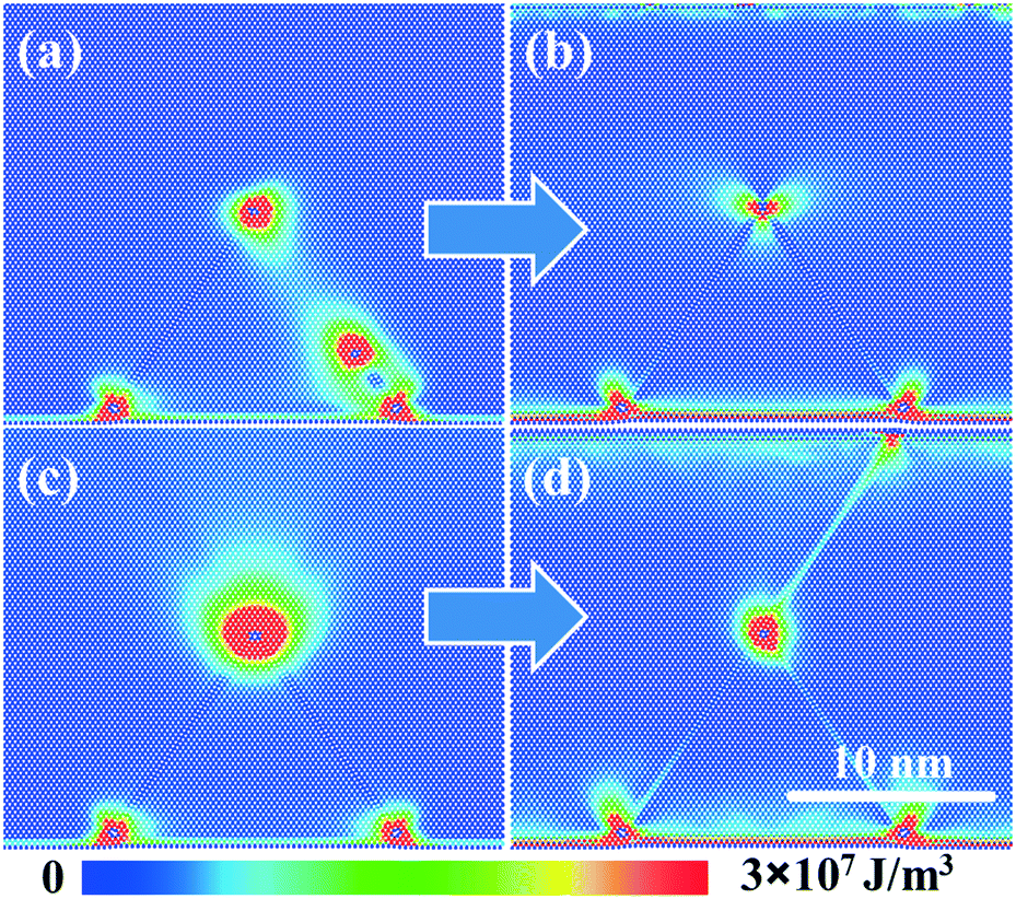 | ||
| Fig. 4 Elastic energy maps corresponding to the interaction of closely spaced 30° partial dislocations with opposite (a and b) and equal (c and d) screw components of Burgers vectors in the initial (a and c) and final (b and d) states of evolution. | ||
On the contrary, 30° PDs with equal screw components of their Burgers vectors, gliding in the (11) and (11) planes would combine Burgers vectors as  (or
(or  ). Using the b2 criterion, we conclude that these reactions are unfavorable leading to the increase in the elastic energy of the crystal. The energy maps corresponding to the configurations in Fig. 3d and f are shown in Fig. 4c and d, respectively. The elastic energy of the crystal decreases upon separation of the mentioned dislocations. Therefore, 30° PDs with equal screw components of Burgers vectors would repulse each other within the interaction radius. One of them would advance and glide toward the 3C-SiC surface, while the other one would stop at the disconnection of the slip plane created by the SF left by the former dislocation. As a result, the “λ”-shaped SF intersection would be formed with the exclusion of only one stacking fault from the extension.
The results obtained in this study give an insight into the exploitation of the annihilation mechanism to reduce the concentration of stacking faults in epitaxial 3C-SiC layers on Si(001) substrates. Efficient SF elimination may be achieved by manipulation of stress in the 3C-SiC layers during deposition, e.g. by the optimization of temperature at different deposition stages, to limit the propagation of the 30° partial dislocations leading the SFs. Attenuation of stress would also reduce the generation of partial dislocations and associated stacking faults at the 3C-SiC surface and their motion to the bulk, thus contributing to the minimization of SF concentration.
Conclusions
In conclusion, we have studied the mechanism of the annihilation and formation of the intersection patterns of stacking faults in 3C-SiC layers epitaxially grown on Si(001) substrates by MD simulations. We have shown that the annihilation of stacking faults lying in opposite {111} planes during 3C-SiC layer growth is determined by the motion and interaction of 30° Shockley partial dislocations leading the SFs under slightly compressive strain conditions. The key parameters characterizing the SF annihilation process are the distance between the leading PDs and the mutual orientation of their Burgers vectors. 30° partials with opposite screw components of Burgers vectors interact attractively at small distances (∼15 nm or less), forming a Lomer–Cottrell lock at the “inverted V” SF intersection. As a result, two SFs are annihilated. On the other hand, “λ”-shaped SF intersection with the annihilation of only one stacking fault is obtained when SF leading dislocations are too far apart (more than ∼15 nm) and do not interact efficiently or they have equal screw components of Burgers vectors causing repulsion between them. The obtained results have an important implication for the elaboration of the improved methods of the reduction of SF concentrations in epitaxial 3C-SiC layers on Si(001) substrates for the power device applications.Author contributions
Conceptualization, A. S. and A. M.; funding acquisition, F. L. V. and L. M.; investigation, A. S.; methodology, A. S., A. M. and L. B.; project administration, F. L. V. and L. M.; resources, M. Z., C. B., M. M. and D. C.; software, A. S. and L. B.; supervision, L. M.; writing – original draft, A. S.; writing – review and editing, A. M., L. B., M. Z. and L. M.Conflicts of interest
There are no conflicts to declare.Acknowledgements
Authors acknowledge EU for funding the CHALLENGE project (3C-SiC Hetero-epitaxiALLy grown on silicon compliancE substrates and 3C-SiC substrates for sustaiNable wide-band-Gap power devices) within the EU's H2020 framework program for research and innovation under grant agreement no. 720827.References
- D. J. Young, J. Du, C. A. Zorman and W. H. Ko, IEEE Sens. J., 2004, 4, 464 CrossRef CAS
.
-
S. E. Saddow and A. Agarwal, Advances in Silicon Carbide Processing and Applications, Artech House Publisher, Boston, 2004 Search PubMed
- T. J. Fawcett and J. T. Wolan, Appl. Phys. Lett., 2006, 89, 182102 CrossRef
- V. V. Afanasev, M. Bassler, G. Pensl and M. Schulz, Phys. Status Solidi A, 1997, 162, 321 CrossRef CAS
- M. Mehregany, C. A. Zorman, S. Roy, A. J. Fleischman, C.-H. Wu and N. Rajan, Int. Mater. Rev., 2000, 45, 85 CrossRef CAS
- M. Ruff, H. Mitlehner and R. Helbig, IEEE Trans. Electron Devices, 1994, 41, 1040 CrossRef CAS
- F. Giannazzo, G. Greco, S. D. Franco, P. Fiorenza, I. Deretzis, A. L. Magna, C. Bongiorno, M. Zimbone, F. L. Via, M. Zielinski and F. Roccaforte, Adv. Electron. Mater., 2020, 6, 1901171 CrossRef CAS
- X. Song, J. F. Michaud, F. Cayrel, M. Zielinski, M. Portail, T. Chassagne, E. Collard and D. Alquier, Appl. Phys. Lett., 2010, 96, 142104 CrossRef
- E. Scalise, L. Barbisan, A. Sarikov, F. Montalenti, L. Miglio and A. Marzegalli, J. Mater. Chem. C, 2020, 8, 8380 RSC
- F. La Via, A. Severino, R. Anzalone, C. Bongiorno, G. Litrico, M. Mauceri, M. Schoeler, P. Schuh and P. Wellmann, Mater. Sci. Semicond. Process., 2018, 78, 57 CrossRef CAS
- M. Zimbone, E. G. Barbagiovanni, C. Bongiorno, C. Calabretta, L. Calcagno, G. Fisicaro, A. L. Magna and F. L. Via, Cryst. Growth Des., 2020, 20, 3104 CrossRef CAS
- G. Fisicaro, C. Bongiorno, I. Deretzis, F. Giannazzo, F. L. Via, F. Roccaforte, M. Zielinski, M. Zimbone and A. La Magna, Appl. Phys. Rev., 2020, 7, 021402 CAS
- H. Nagasawa, R. Gurunathan and M. Suemitsu, Mater. Sci. Forum, 2015, 821–823, 108 Search PubMed
- H. Nagasawa, K. Yagi and T. Kawahara, J. Cryst. Growth, 2002, 237–239, 1244 CrossRef CAS
- Y. Sun, S. Izumi, S. Sakai, K. Yagi and H. Nagasawa, Phys. Status Solidi B, 2012, 249, 555 CrossRef CAS
- G. D'Arrigo, A. Severino, G. Milazzo, C. Bongiorno, N. Piluso, G. Abbondanza, M. Mauceri, G. Condorelli and F. La Via, Mater. Sci. Forum, 2010, 645–648, 135 Search PubMed
- M. Zimbone, M. Zielinski, C. Bongiorno, C. Calabretta, R. Anzalone, S. Scalese, G. Fisicaro, A. La Magna, F. Mancarella and F. La Via, Materials, 2019, 12, 3407 CrossRef CAS
- H. von Känel, L. Miglio, D. Crippa, T. Kreiliger, M. Mauceri, M. Puglisi, F. Mancarella, R. Anzalone, N. Piluso and F. La Via, Mater. Sci. Forum, 2015, 821–823, 193 Search PubMed
- M. Meduña, T. Kreiliger, I. Prieto, M. Mauceri, M. Puglisi, F. Mancarella, F. La Via, D. Crippa, L. Miglio and H. von Känel, Mater. Sci. Forum, 2016, 858, 147 Search PubMed
- V. Papaioannow, P. Komninou, G. P. Dimitrakopulos, K. Zekentes, B. Pecz, T. Karakostas and J. Stoemenos, Diamond Relat. Mater., 1997, 6, 1362 CrossRef
- J. Yamasaki, S. Inamoto, Y. Nomura, H. Tamaki and N. Tanaka, J. Phys. D: Appl. Phys., 2012, 45, 494002 CrossRef
- S. Plimpton, J. Comput. Phys., 1995, 117, 1 CrossRef CAS
- P. Vashishta, R. K. Kalia, A. Nakano and J. P. Rino, J. Appl. Phys., 2007, 101, 103515 CrossRef
- A. Sarikov, A. Marzegalli, L. Barbisan, E. Scalise, F. Montalenti and L. Miglio, Modell. Simul. Mater. Sci. Eng., 2020, 28, 015002 CrossRef CAS
- A. Stukowski, Modell. Simul. Mater. Sci. Eng., 2012, 18, 015012 CrossRef
-
J. P. Hirth and J. Lotte, Theory of Dislocations, Krieger Publishing Company, Malabar, 1982 Search PubMed
- W. Cai, V. V. Bulatob, J. Chang, J. Li and S. Tip, Philos. Mag., 2003, 83, 539 CrossRef CAS
- A. Sarikov, A. Marzegalli, L. Barbisan, F. Montalenti and L. Miglio, Materials, 2019, 12, 3027 CrossRef CAS
- D. Méndez, A. Aouni, F. M. Morales, F. J. Pacheco, D. Araújo, E. Bustarret, G. Ferro and Y. Monteil, Phys. Status Solidi A, 2005, 202, 561 CrossRef
-
A. Taylor and R. M. Jones, Silicon Carbide - A High Temperature Semiconductor, Pergamon Press, London, 1960 Search PubMed
- W. M. Yim and R. J. Paff, J. Appl. Phys., 1974, 45, 1456 CrossRef CAS
- B. Yang, H. Zhuang, J. Li, N. Huang, L. Liu, K. Tai and X. Jiang, CrystEngComm, 2016, 18, 6817 RSC
- W. Wegscheider and S. Cerva, J. Vac. Sci. Technol., B, 1993, 11, 1056 CrossRef CAS
- E. Scalise, A. Marzegalli, F. Montalenti and L. Miglio, Phys. Rev. Appl., 2019, 12, 021002 CrossRef CAS
| This journal is © The Royal Society of Chemistry 2021 |