
Biocompatible MOFs with high absolute quantum yield for bioimaging in the second near infrared window†
Dorina F.
Sava Gallis
 *a,
Kimberly S.
Butler
b,
Lauren E. S.
Rohwer
c,
Amber A.
McBride
b,
Grace
Vincent
a,
Casey V.
Chong
a,
Charles J.
Pearce
a and
Ting S.
Luk
d
*a,
Kimberly S.
Butler
b,
Lauren E. S.
Rohwer
c,
Amber A.
McBride
b,
Grace
Vincent
a,
Casey V.
Chong
a,
Charles J.
Pearce
a and
Ting S.
Luk
d
aNanoscale Sciences Department, Sandia National Laboratories, Albuquerque, NM 87185, USA. E-mail: dfsava@sandia.gov
bNanobiology Department, Sandia National Laboratories, Albuquerque, NM 87185, USA
cMicrosystems Integration Department, Sandia National Laboratories, Albuquerque, NM 87185, USA
dNanostructure Physics Department, Sandia National Laboratories, Albuquerque, NM 87185, USA
First published on 24th July 2018
Abstract
Here we detail a study highlighting the correlation between particle size and absolute quantum yield (QY) in novel mixed metal near-infrared (NIR) emitting metal–organic frameworks (MOFs) materials. The nanoscale analogue in this series presents a QY of 6.3%, the highest of any NIR emitting MOFs reported to date.
Advancing the state-of-the-art of in vivo imaging techniques is an emerging research topic in recent years.1–3 In particular, there is extensive interest to develop near infrared (NIR) emitting materials with emission properties between 1000–1400 nm, in the second NIR window (NIR-II).4,5 Imaging in this regime is non-invasive, offers improved sensitivity and signal to noise ratio, and deeper tissue penetration depth. Additionally, scattering and absorption by blood and tissues is reduced and contribution from background autofluorescence is negligible in this window.6–8
A number of important pre-requisites should be accounted for in the design of fluorescent probes for NIR-II bioimaging: good biocompatibility, stability against photobleaching, excitation in the NIR to avoid autofluorescence, as well as ease of synthesis and functionalization. Lastly, targeting bright NIR-II emitters with high quantum yield (QY) is critical, to facilitate short exposure times during imaging.
Existing NIR-II emitters include dyes, carbon nanotubes, organic fluorophores, and quantum dots (primarily lead sulfide and indium arsenide).1,2 Many of these systems do not concurrently meet the criteria mentioned above. Some of the limitations relate to inherent toxicity which requires additional post-synthetic modifications.9 Generally, the synthesis of these materials is complex (multi-step) and/or requires energy intensive processes. Additionally, the aqueous media stability, necessary for biological use, is a concern in many systems.10 Finally, the QY of the vast majority of well-studied NIR-II emitters is very low (0.05–0.1%), thereby precluding practical applications.11
In this context, metal–organic frameworks (MOFs) represent a class of materials that can offer significant advantages, as facilitated by their rich chemistry and hybrid organic–inorganic nature.12 MOFs are generally obtained via one step straight forward synthesis, and they allow fine tuning engineering of the metal and linker components, and consequently that of the charge transfer between the two.13–16
We recently reported a novel family of biocompatible luminescent MOFs based on rare earth (RE) metal ions and 2,5-dihydroxyterephthalic acid (DOBDC) linker, presenting tunable emission properties over the entire NIR regime (650–1400 nm).17
The materials are based on a hexanuclear metal cluster, Fig. 1a and the periodic arrangement of these nodes results in a three-dimensional framework, possessing permanent porosity, Fig. 1b. Importantly, the Eu-based nanoparticle analogue in this materials platform was demonstrated to be cell permeable in individual HeLa human cervical cancer epithelial cells and RAW 264.7 mouse macrophage cells. Also, its luminescent properties within cells were retained up to 48 h post incubation.
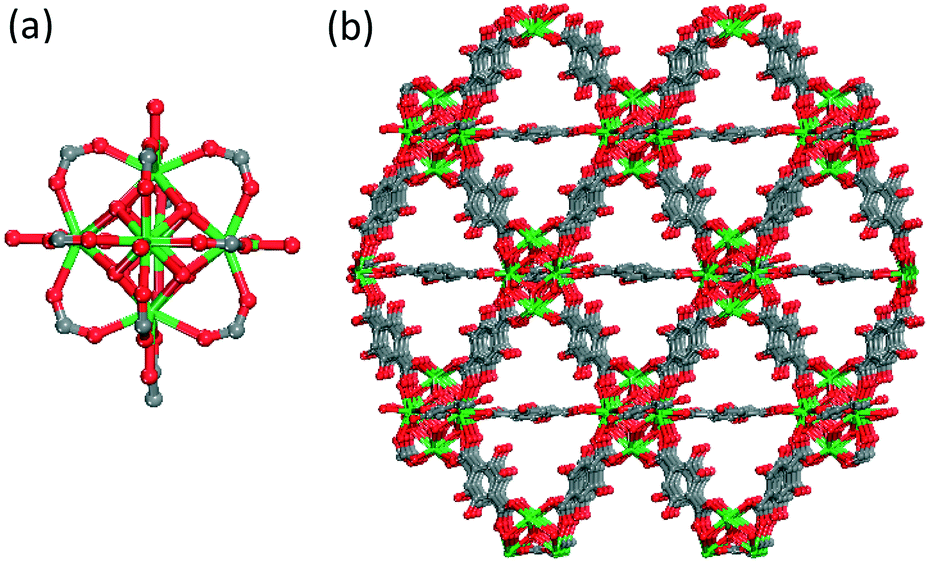 | ||
| Fig. 1 Ball-and-stick schematic depiction of (a) hexanuclear cluster and (b) 3-periodic representation of the NdYbDOBDC structure. Hydrogen atoms and pore solvent molecules have been omitted for clarity; atom color scheme: metal (Nd, Yb) = green; C = grey, O = red. | ||
Here, we extend our original studies to focus on a mixed composition of Yb and Nd, isostructural with the material system described above. The composition was judiciously selected so that the collective emission properties of the two metals are spanning over the entire second NIR-II window. Emphasis is placed on investigating the particle size effect on QY, along with the testing the biocompatibility with relevant epithelial and macrophage cell lines.
Experiments were designed accordingly, and three different particles sizes of YbNdDOBDC materials are reported here. First, micron sized particles of ∼30 μm (compound 1) were synthesized via conventional techniques (115 °C in the oven, 3 days). Second, ∼5 μm (compound 2) particles were obtained using microwave irradiation (175 °C, 15 min).
Lastly, various heating times were investigated to further reduce the particle size into the nano regime. We found that heating time is the most critical factor that controls the particle size for this materials system, when using microwave irradiation. Specifically, a unique heating program at 175 °C for 3 minutes, followed by a cool down to 40 °C, and immediate subsequent heating at 175 °C for 1 additional minute results in homogeneous particles of ∼100 nm (compound 3).
Electron microscopy techniques were used to characterize the morphology and particle size of the materials. For compounds 1 and 2, scanning electron micrographs (SEM) reveal polyhedral single crystal with average particle sizes of ∼30 μm for 1 (Fig. 2a), and 5 μm, respectively for 2 (Fig. 2b).
 | ||
| Fig. 2 SEM-EDS analyses on (a) compound 1; (b) compound 2; (c) TEM on compound 3. | ||
Importantly, energy dispersive spectroscopy (EDS) elemental mapping confirms a homogeneous distribution of the Yb and Nd signals in these materials. Transmission electron microscopy (TEM) was used to image the nanoparticle analogue, compound 3. The particles are roughly 100 nm in diameter and display rhombic morphology. Further SEM-EDS analyses (Fig. S1–S3†) confirmed all three compounds have similar doping levels of Yb and Nd in their structures, with a consistent ratio of Yb/Nd = 0.5, Yb0.33Nd0.67DOBDC.
Additional structural characterization techniques were used to assess the materials' properties. Fig. 3a shows the good correlation between the calculated and experimental powder X-ray diffraction patterns, highlighting the phase purity of the three compounds.
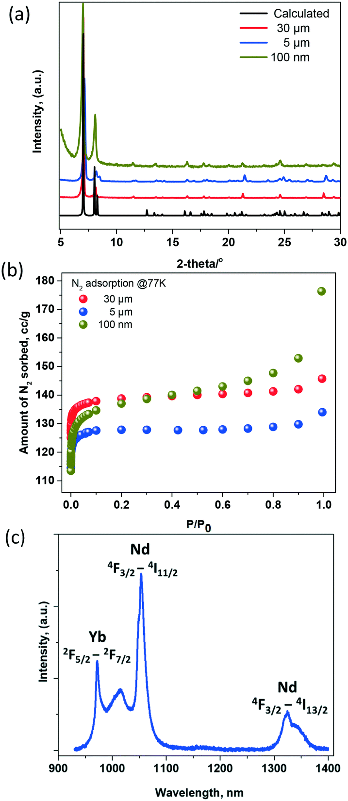 | ||
| Fig. 3 Structural characterization of NdYbDOBDC with 3 distinct particle sizes (30 μm, 5 μm, 100 nm); (a) X-ray powder diffraction and (b) N2 adsorption isotherm measured at 77 K; (c) representative PL emission spectra highlighting characteristic transitions for Nd3+ and Yb3+ ions, λex = 808 nm. | ||
To evaluate the accessible porosity in these materials, the as-made samples were washed 3× with dimethylformamide (DMF) and were soaked in methanol (MeOH) for 3 days, with the solvent replenished twice daily. The MeOH-exchanged samples were then activated at 100 °C for 16 h on a Micromeritics ASAP 2020 porosity analyser. Nitrogen adsorption isotherms were measured at 77 K on fully evacuated samples, Fig. 3b. As expected, the calculated BET surface area is similar amongst the three analogues, 580 m2 g−1 for compound 1, 536 for compound 2 m2 g−1 and 555 m2 g−1 for compound 3, and is comparable with that of the originally reported RE platform.15
A representative photoluminescence (PL) emission spectrum for the YbNdDOBDC compounds when excited at 808 nm is shown in Fig. 3c. Nd ions are directly excited at this wavelength, displaying emission bands at ∼1060 nm (4F3/2–4I11/2 transitions) and at 1325 nm (4F3/2–4I13/2 transitions).17–19 Yb3+ emission is noted at 980 nm, via direct energy transfer from Nd3+ ions. Specifically, the 4F5/2 levels in Nd3+ions are directly excited at 808 nm, decaying nonradiatively to the 4F3/2 emitting level and subsequently engaging in energy transfer to the 2F5/2 energy level of Yb3+ ions.20,21
Absolute QY measurements were conducted at room temperature using an integrating sphere.22 Relative QY measurements of NIR-II materials are subject to errors due to the unreliable QY values accepted for the materials used as standards. For example, the QY of IR-26, a well-studied NIR-II dye has been revisited in recent years and shown to be 0.05–0.07%,11,23,24 roughly ten times less than originally reported, 0.5%.11,25
It was found the QY of compounds 1, 2, 3 measured in the solid state was 1.1%, 2% and 5.8%, respectively. This result differs from trends observed in other rare earth-based emitters (such as phosphors).26 However, it aligns with other studies of semiconductor quantum dots, that also showed an increase in QY with a reduction in particle size.23 In that case, nonradiative transition between electronic states and energy transfer to ligand vibrations, justified the size dependence. It should be noted that the measurements that established the trend reported here were performed in the solid state. The vast majority of QY measurements we are aware of are conducted on colloidal suspensions of nanoparticles. Therefore, light scattering from the solid-state samples could be prone to dependency on the particle size and the heterogeneity in sample packing. Future studies need to be conducted on related MOF systems, in order to gather a better understanding of the mechanism responsible for trend observed here.
Importantly, the absolute QY of compound 3 exceeds many times that of dyes,20,23 and carbon nanotubes27 and represents the highest QY of any NIR emitting MOFs reported to date. To the best of our knowledge, the previously highest QY reported for a NIR-emitting MOF was 4.55 × 10⁻², for crystals suspended in DMF.28
The QY of compound 3 as function of solvent was evaluated next. The solid sample was dispersed in chloroform (CHCl3), isopropyl alcohol (IPA), water (H2O), DMF, dimethyl sulfoxide (DMSO), and acetone (C3H6O), Table 1.
| Solvent | CHCl3 | IPA | H2O | DMF | DMSO | C3H6O |
|---|---|---|---|---|---|---|
| QY | 6% | 5.4% | 4.4% | 5.2% | 6% | 6.3% |
Remarkably, the QY is mainly preserved or improved in all solvents, with the exception of water. Similar observations were noted in other studies; however, in that case, the QY reduction in water was a lot more drastic.29 The highest QY value, 6.3%, was observed for the acetone suspended compound 3.
In order to assess the significance of these materials for biological imaging applications, a series of relevant properties were further assessed. As most, if not all, bioimaging techniques require dispersion in a biologically relevant solution, measurement of the hydrodynamic size is important to understanding the behavior of the nanoMOFs in biological environments. As such, the hydrodynamic size of the nanoparticle analogs was measured by dynamic light scattering (DLS), Table 2.
| Solution | Hydrodynamic size (nm) | PdI | Zeta potential (mV) |
|---|---|---|---|
| 3 in H2O | 420.7 (±84.4) | 0.213 (±0.09) | 1.97 (±0.14) |
| 3 in 1× PBS pH 7.2 | 963.7 (±140.1) | 0.446 (±0.15) | 1.40 (±0.11) |
| 3 in media + 10% FBS | 1021 (±254.0) | 0.784 (±0.36) | Not measured |
It was found that the particle size in all measured solutions (water, PBS, media + 10% FBS) was larger than the TEM based measurement. Larger sizes are commonly observed when assessing size of nanoparticles by DLS compared to TEM.30 This increase in size is likely due to two factors: agglomeration of the YbNd nanoMOFs in solution and the nature of the DLS measurement itself. Unlike TEM, DLS measures the hydrodynamic diameter of the particles in solution, including the hydration layer and any associated proteins or stabilizers absorbed from the solution, leading to larger particle sizes than direct imaging measurements, like TEM.30,31 Additionally, the DLS measurement is based on light scattering, which is proportional to the sixth power of the particle diameter, and in the case of a polydisperse particle or agglomeration, can result in the larger particles strongly influencing the final size measurement.31 A significant increase in size between DLS and TEM measurements of nano-sized MOFs has also previously been reported.17,32
The particle size increase is accentuated in biologically relevant solutions, such as PBS and media with FBS. This size increase correlates with amplified aggregation, most likely due to the particles' interaction with complex components in PBS and cell culture media. Increased aggregation of MOFs in both PBS and media has been observed previously.17,33
The observed size increase may also be influenced by the pH of the dispersant solution, as colloids lose stability and can agglomerate when the pH is close to the isoelectric point.30 The zeta potential of the YbNd nanoMOFs in PBS at pH 7.2 and water at pH 7.0 are close to neutral suggesting pH 7.0 is near the isoelectric point for these MOFs.
To evaluate this possibility, the zeta potential was examined in PBS with altered pH revealing zeta potentials of 4.87 (±0.158) and −13.2 (±1.39) at pH 5.4 and 9.4 respectively, suggesting the isoelectric point of the YbNd nanoMOFs is close to pH 7. The hydrodynamic size and the zeta potential of the YbNd nanoMOFs suggest that additional surface modifications might be needed to improve the dispersion and stability of the particles in biologically relevant solutions and pH for biological applications.
Further, the particles were assessed for biocompatibility as measured by alterations in cell viability to mammalian cells. A human epithelial cell line (A549) and a mouse macrophage cell line (RAW 264.7) were chosen as representative cell lines as epithelial cells are common targets for imaging and macrophages are involved in the clearance of injected nanomaterials. Cell viability was assessed after both 24 and 48 h of incubation with both micron-sized (compound 1), and nano-sized (compound 3) materials, Fig. 4. The micron-sized MOF particles demonstrated low cytotoxicity to both cell lines with greater than 80% survival at 100 μg mL−1 at both 24 and 48 h exposures. The low level of cytotoxicity of micron scale MOFs is consistent with previous studies with a variety of MOF compositions.17,34
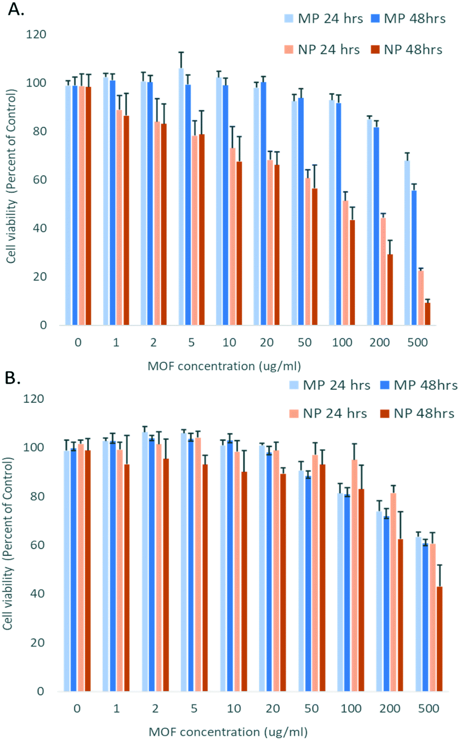 | ||
| Fig. 4 Cellular viability of (A) RAW 264.7 mouse macrophage cells and (B) A549 human lung epithelial cells after 24 h and 48 h of incubation with YbNd micron-sized MOF (MP) and nano-sized MOF (NP). | ||
Additionally, the nano-sized particles demonstrated low cytotoxicity to the epithelial cell line, with greater than 80% of cells surviving at both 24 and 48 h with doses up to 100 μg mL−1 and demonstrating no significant difference in toxicity between the nano- and micron-sized particles with epithelial cell exposure.
The macrophage line showed significant differences in toxicity profile between the micron- and nano-sized particles. Macrophages exposed to the micron-sized particles had survival greater than 80% after 24 or 48 h exposure up to 200 μg mL−1. In contrast, considerable toxicity was present with the nano-sized with a dose as low as 10 μg mL−1, reducing viability to 80% at 24 h. This difference is illustrated by calculating the half maximal inhibitory concentration (IC50) values for cell viability inhibition by the YbNd MOFs. IC50 values are a common measure of potency of a substance in inhibiting cell growth. The IC50 value exceeded the experimental maximal dose of 500 μg mL−1 for the A549 cells with both the micron and nano-sized MOFs and for the RAW 264.7 cells exposed to the micron-sized MOFs. For the RAW 264.7 exposed to the nano-sized YbNd MOFs the IC50 value was reduced to 152.5 μg mL−1.
Similar to the previous study with MOFs, the toxicity of the nanosized YbNd MOF was significantly enhanced in the macrophage cell type compared to the epithelial cell type. The IC50 value of the YbNd nanoMOF to macrophages is within the range of toxicities previously seen with a variety of other nanosized MOFs made from Zr, Zn and Fe metals and linkers, which ranged from 25–700 μg mL−1.35
To be noted, there are a number of viable options that can effectively mitigate the toxicity of the YbNd nanoMOFs, including the addition of a biocompatible coating to the MOF surface, thereby altering the interaction with the macrophage cells.35,36
Conclusions
The NIR photoluminescence, absolute quantum yield and biocompatibility with epithelial and macrophage cells were evaluated in a mixed YbNd-based MOF platform. This material displays emission properties over the entire NIR-II region, ∼1000–1400 nm and has a quantum yield of 6.3%. This is the highest QY reported for any NIR-emitting MOFs to date. Importantly, the high QY is maintained in a variety of solvents, qualifying this material as very promising amongst all other known NIR-II fluorophores.Cell viability was assessed after both 24 and 48 h of incubation. Micron sized particles present limited toxicity levels for both cell lines tested here, A549 and RAW 264.7. Consistent with previous findings, the nanoscale MOFs were highly biocompatible with the epithelial cell lines (A549), but presented noticeable toxicity to macrophage (RAW 267.4) cells. However, the toxicity for the YbNd-based nanoMOFs did not exceed the toxicity observed for other MOFs with macrophage cells.
In an effort to establish a fundamental understanding between structural features in NIR-emitting MOFs and absolute quantum yield, current work is further investigating the cumulative effect of the coordination geometry of mixed YbNd metal clusters in MOFs, linker identity (including functional groups), porosity/pore environment and emission efficiency. In parallel, we plan to pursue both in vitro and in vivo imaging NIR imaging experiments.
Conflicts of interest
There are no conflicts to declare.Acknowledgements
This work is supported by the Laboratory Directed Research and Development Program at Sandia National Laboratories and was performed, in part, at the Center for Integrated Nanotechnologies, an Office of Science User Facility operated for the U.S. Department of Energy (DOE) Office of Science. Sandia National Laboratories is a multimission laboratory managed and operated by National Technology and Engineering Solutions of Sandia, LLC., a wholly owned subsidiary of Honeywell International, Inc., for the U.S. Department of Energy's National Nuclear Security Administration under contract DE-NA-0003525. This paper describes objective technical results and analysis. Any subjective views or opinions that might be expressed in the paper do not necessarily represent the views of the U.S. Department of Energy or the United States Government.References
- Z. Guo, S. Park, J. Yoon and I. Shin, Chem. Soc. Rev., 2014, 43, 16–29 RSC
.
- V. J. Pansare, S. Hejazi, W. J. Faenza and R. K. Prud'homme, Chem. Mater., 2012, 24, 812–827 CrossRef PubMed
- E. Thimsen, B. Sadtler and M. Y. Berezin, Nanophotonics, 2017, 6, 1043–1054 Search PubMed
- E. Hemmer, A. Benayas, F. Legare and F. Vetrone, Nanoscale Horiz., 2016, 1, 168–184 RSC
- A. M. Smith, M. C. Mancini and S. Nie, Nat. Nanotechnol., 2009, 4, 710–711 CrossRef PubMed
- K. Welsher, S. P. Sherlock and H. Dai, Proc. Natl. Acad. Sci. U. S. A., 2011, 108, 8943–8948 CrossRef PubMed
- G. Hong, J. C. Lee, J. T. Robinson, U. Raaz, L. Xie, N. F. Huang, J. P. Cooke and H. Dai, Nat. Med., 2012, 18, 1841 CrossRef PubMed
- G. Hong, S. Diao, J. Chang, A. L. Antaris, C. Chen, B. Zhang, S. Zhao, D. N. Atochin, P. L. Huang, K. I. Andreasson, C. J. Kuo and H. Dai, Nat. Photonics, 2014, 8, 723 CrossRef PubMed
- Y. Kong, J. Chen, H. Fang, G. Heath, Y. Wo, W. Wang, Y. Li, Y. Guo, S. D. Evans, S. Chen and D. Zhou, Chem. Mater., 2016, 28, 3041–3050 CrossRef PubMed
- B. Dong, C. Li, G. Chen, Y. Zhang, Y. Zhang, M. Deng and Q. Wang, Chem. Mater., 2013, 25, 2503–2509 CrossRef
- O. T. Bruns, T. S. Bischof, D. K. Harris, D. Franke, Y. Shi, L. Riedemann, A. Bartelt, F. B. Jaworski, J. A. Carr, C. J. Rowlands, M. W. B. Wilson, O. Chen, H. Wei, G. W. Hwang, D. M. Montana, I. Coropceanu, O. B. Achorn, J. Kloepper, J. Heeren, P. T. C. So, D. Fukumura, K. F. Jensen, R. K. Jain and M. G. Bawendi, Nat. Biomed. Eng., 2017, 1, 0056 CrossRef PubMed
- H. Furukawa, K. E. Cordova, M. O'Keeffe and O. M. Yaghi, Science, 2013, 341, 1230444 CrossRef PubMed
- M. D. Allendorf, C. A. Bauer, R. K. Bhakta and R. J. T. Houk, Chem. Soc. Rev., 2009, 38, 1330–1352 RSC
- Y. Cui, Y. Yue, G. Qian and B. Chen, Chem. Rev., 2012, 112, 1126–1162 CrossRef PubMed
- D. F. Sava, L. E. S. Rohwer, M. A. Rodriguez and T. M. Nenoff, J. Am. Chem. Soc., 2012, 134, 3983–3986 CrossRef PubMed
- D. F. Sava Gallis, L. E. S. Rohwer, M. A. Rodriguez and T. M. Nenoff, Chem. Mater., 2014, 26, 2943–2951 CrossRef
- D. F. Sava Gallis, L. E. S. Rohwer, M. A. Rodriguez, M. C. Barnhart-Dailey, K. S. Butler, T. S. Luk, J. A. Timlin and K. W. Chapman, ACS Appl. Mater. Interfaces, 2017, 9, 22268–22277 CrossRef PubMed
- J. Yang, Q. Yue, G.-D. Li, J.-J. Cao, G.-H. Li and J.-S. Chen, Inorg. Chem., 2006, 45, 2857–2865 CrossRef PubMed
- X.-C. Chai, Y.-Q. Sun, R. Lei, Y.-P. Chen, S. Zhang, Y.-N. Cao and H.-H. Zhang, Cryst. Growth Des., 2010, 10, 658–668 CrossRef
- D. Shi and Y. Zhao, J. Rare Earths, 2016, 34, 368–373 CrossRef
- R. Balda, J. Ignacio Peña, M. Angeles Arriandiaga and J. Fernández, Opt. Express, 2010, 18, 13842–13850 CrossRef PubMed
- L. S. Rohwer and J. E. Martin, J. Lumin., 2005, 115, 77–90 CrossRef
- O. E. Semonin, J. C. Johnson, J. M. Luther, A. G. Midgett, A. J. Nozik and M. C. Beard, J. Phys. Chem. Lett., 2010, 1, 2445–2450 CrossRef
- S. Hatami, C. Wurth, M. Kaiser, S. Leubner, S. Gabriel, L. Bahrig, V. Lesnyak, J. Pauli, N. Gaponik, A. Eychmuller and U. Resch-Genger, Nanoscale, 2015, 7, 133–143 RSC
- B. L. Wehrenberg, C. Wang and P. Guyot-Sionnest, J. Phys. Chem. B, 2002, 106, 10634–10640 CrossRef
- W.-N. Wang, W. Widiyastuti, T. Ogi, I. W. Lenggoro and K. Okuyama, Chem. Mater., 2007, 19, 1723–1730 CrossRef
- K. Welsher, Z. Liu, S. P. Sherlock, J. T. Robinson, Z. Chen, D. Daranciang and H. Dai, Nat. Nanotechnol., 2009, 4, 773–780 CrossRef PubMed
- T.-Y. Luo, C. Liu, S. V. Eliseeva, P. F. Muldoon, S. Petoud and N. L. Rosi, J. Am. Chem. Soc., 2017, 139, 9333–9340 CrossRef PubMed
- Z. Lei, X. Li, X. Luo, H. He, J. Zheng, X. Qian and Y. Yang, Angew. Chem., Int. Ed., 2017, 56, 2979–2983 CrossRef PubMed
- S. Bhattacharjee, J. Controlled Release, 2016, 235, 337–351 CrossRef PubMed
- H. Fissan, S. Ristig, H. Kaminski, C. Asbach and M. Epple, Anal. Methods, 2014, 6, 7324–7334 RSC
- P. Hirschle, T. Prei, F. Auras, A. Pick, J. Volkner, D. Valdeperez, G. Witte, W. J. Parak, J. O. Radler and S. Wuttke, CrystEngComm, 2016, 18, 4359–4368 RSC
- C. Orellana-Tavra, R. J. Marshall, E. F. Baxter, I. A. Lazaro, A. Tao, A. K. Cheetham, R. S. Forgan and D. Fairen-Jimenez, J. Mater. Chem. B, 2016, 4, 7697–7707 RSC
- Q. Hu, J. Yu, M. Liu, A. Liu, Z. Dou and Y. Yang, J. Med. Chem., 2014, 57, 5679–5685 CrossRef PubMed
- C. Tamames-Tabar, D. Cunha, E. Imbuluzqueta, F. Ragon, C. Serre, M. J. Blanco-Prieto and P. Horcajada, J. Mater. Chem. B, 2014, 2, 262–271 RSC
- R. Liu, T. Yu, Z. Shi and Z. Wang, Int. J. Nanomed., 2015, 11, 1187–1200 Search PubMed
Footnote |
| † Electronic supplementary information (ESI) available. See DOI: 10.1039/c8ce00909k |
| This journal is © The Royal Society of Chemistry 2018 |