
One-pot synthesis of hierarchical-pore metal–organic frameworks for drug delivery and fluorescent imaging†
Xuechuan
Gao‡
a,
Yuewu
Wang‡
b,
Guanfeng
Ji
a,
Ruixue
Cui
a and
Zhiliang
Liu
 *a
*a
aCollege of Chemistry and Chemical Engineering, Inner Mongolia University, Hohhot, 010021, P. R. China. E-mail: cezlliu@imu.edu.cn
bThe Center for New Drug Safety Evaluation and Research, Inner Mongolia Medical University, Hohhot, 010021, P. R. China
First published on 17th January 2018
Abstract
Metal–organic frameworks (MOFs) have attracted significant interest for drug delivery. However, MOFs usually have micropores smaller than 2 nm, restraining larger drug molecules from entering into the pores of MOFs, restricting their practical application as drug carriers. Here we demonstrate a novel one-step approach to synthesize a fluorescent hierarchical-pore metal–organic framework (H-MOF), which is realized by assembling a MOF in an aqueous solution containing rhodamine b (RhB) as a modulator and a fluorescent imaging reagent. The as-synthesized fluorescent H-MOF can not only serve as a substrate to in situ load micromolecule and macromolecular drugs simultaneously, but can also efficiently deliver the drugs into cells. The red fluorescence of RhB remains in the H-MOF, avoiding the interference of auto-fluorescence in vivo imaging and realizing high quantum yield and low-background imaging. The low cytotoxicity, good biocompatibility and high imaging efficiency of the fluorescence H-MOF are confirmed using murine gastric cancer 803 (MGC-803) cells and human airway smooth muscle cell (HASMC) as modes. Good stability and distribution in vivo are confirmed using naked mouse as modes. Taken together, we demonstrate the possibility of using one-step method to obtain fluorescent H-MOF, aiming for loading various drug molecules and bioimaging, which probably is useful for some specific requirements of pharmaceuticals.
Introduction
Metal–organic frameworks (MOFs) are a new class of high performance materials with permanent well-ordered pore systems and large specific surface area.1,2 This specific character has made the application of MOFs in drug delivery a major topic of interest in the last few years.4–6 Additionally, in contrast to traditional porous materials, MOFs offer a number of chemically reactive sites in their pores, exhibiting outstanding performances. MOFs also possess a highly molecule designable nature in terms of their pore size and pore wall, making MOFs materials beneficial for drug delivery.7–9 Since the ability of MOFs to be used as drug delivery carriers was demonstrated by Férey and co-workers for the first time,10 encouraging efforts concentrated on using MOFs as drug delivery systems have been made and researchers have built high-capacity drug-loading devices for small drug molecules using MOFs.11–15 However, MOFs usually have micropores smaller than 2 nm, restraining larger drug molecules from entering into their pores and reducing the loading efficiency, which restricts their practical application as drug carriers. Considering the limited diffusivity of large drug molecules in the depths of pores, creating some larger pores in conventional MOFs structures is imperative, however challenging, at present.The hierarchical pore architecture, which has at least two levels of organization and interconnectivity of pores in three dimensions,16–18 can solve the larger drug molecular diffusion limitation problem associated with MOFs. Once mesopores are introduced into the primitive microporous MOFs structures, the as-achieved hierarchical-pore MOF (H-MOF) provide better transport for the guest species, especially large molecules and are able to diffuse and load desired amounts of large drug molecules in pores, which is advantageous in complete utilization of materials.
Various synthesis strategies have been elaborately designed and developed for tailoring the pore architecture, such as hard templating, soft templating and indirect templating routes.19–22 However, such methods are usually complicated and based on multi-step synthesis of hierarchical pore nanomaterials. There are few reports on the synthesis of hierarchical pore MOFs. In our study, one-step synthesis, an easy-to-use pathway, is used to obtain fluorescent H-MOF for loading various drug molecules and bioimaging, which is a promising route to broaden the application of MOFs.
One of the most used MOFs is aluminum(III) based MOFs. Aluminum(III) based MOFs are known to be water stable and biocompatible, suggesting their potential as a versatile platform for biomedical applications.23–25 Among the great variety of dyes, Rhodamine B (RhB, Fig. S1A†), as a fluorescence probe with typical red fluorescence emission, is one of the mostly used rhodamines and has been used for diverse purposes in biology and chemistry.26,27 Because of its high fluorescence quantum yield, excellent photophysical properties, tolerance to photobleaching, high color purity, high absorption coefficient in the visible region, good water solubility, low background interference and high photostability, RhB, as a classic laser dye, has become a powerful tool for fluorescence imaging.28,29 RhB dye also appears to be relatively non-toxic when used for biomedical purposes.
5-Fluorouracil (5-FU), as one of the major clinically applied anticancer agents, has been extensively studied for the treatment of a wide variety of tumors.30 Tetracycline hydrochloride (TCH), a board spectrum antibiotic, plays multiple roles as a therapeutic, anti-inflammatory and antibacterial reagent, leading to its extensive utilization for many biomedical uses, especially use against Gram-positive and Gram-negative microorganisms.31 The structures of 5-FU and TCH are shown in Fig. S1B and C.† 5-FU as a small molecule drug and TCH as a macromolecular drug are chosen as model drugs to test the drug loading and release behavior of H-MOF.
Here, the first example of fluorescent H-MOF is built by a one-pot process. We demonstrate that hierarchical pores can be obtained while the dye molecules RhB are encapsulated in Al-MOF, which is known to be a water stable and biocompatible porous material.32,33 The obtained fluorescent H-MOF displays distinct red fluorescence resulting from RhB, demonstrating that RhB molecules are homogeneously distributed within crystals. Meanwhile, the high imaging efficiency, good stability and biocompatibility of fluorescent H-MOF are confirmed using murine gastric cancer 803 (MGC-803) cells, human airway smooth muscle cells (HASMC) and naked mouse as modes. Additionally, fluorescent H-MOF exhibits high drug loading for macromolecular drug TCH and small molecular drug 5-FU as well as satisfying drug release behavior. All in all, this study presents a simple method to develop H-MOF for fluorescence imaging in vivo and delivering of various drugs (Fig. 1).
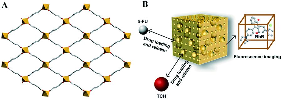 | ||
| Fig. 1 2D plane view of Al-MOF nanocrystalline (A), schematic of RhB@Al-MOF/5-FU/TCH (B). | ||
Experimental section
Material and methods
All the starting reagents and solvents used in this work were of analytical grade and were acquired from commercial sources, and used without further purification unless otherwise noted. Powder X-ray diffraction (XRD) patterns were collected on a PANalytical Empyrean sharp shadow system X-ray diffractometer equipped with Cu Kα radiation (λ = 1.540598 Å) over the 2θ range of 5–80°. Scanning electron microscopy (SEM) was conducted using a HITACHI S-4800 scanning electron microscope, using an accelerating voltage of 200 kV. Fourier transform infrared spectroscopy (FTIR) spectra were assessed by a NEXUS-670 Fourier transform infrared spectrophotometer and photoluminescence spectra were characterized using a Hitachi F-7000 fluorescence spectrophotometer. Thermal gravity analysis (TGA) was carried out using a NETZSCH STA449F3 thermal analyser in the range of 40 °C to 600 °C at a heating rate of 10 °C min−1 under an N2 atmosphere. A laser scanning confocal microscope (OLYMPUS, IX81) was used to confirm cell targeting and cell imaging. UV-visible spectra were recorded on a TU-1901 diode UV-visible spectrophotometer in the wavelength range of 200 to 500 nm.Synthesis of RhB@Al-MOF
The synthesis of RhB@Al-MOFs was done according to a previous work with some modification.32,33 Firstly, 0.72 g AlCl3·6H2O and 0.02 g RhB were dissolved with 15 mL of deionized water and stirred for 30 min. Subsequently, 0.54 g 2-amino terephthalic acid (NH2-H2BDC) was added into the above solution followed by stirring for another 30 min to obtain solution A. 0.72 g urea was dissolved with 15 mL of deionized water to obtain solution B. Lastly, solution B was added to solution A dropwise, and stirred continuously for 24 h at 100 °C. After slowly cooling to room temperature, the obtained products were collected and washed many times with deionized water, and then dried in air at about 70 °C.To investigate the effect of RhB concentration on the formation of hierarchical pores, the amount of RhB was tuned from 0 g, 0.005 g, 0.01 g, to 0.02 g and these were referred to as samples Al-MOF, RhB@Al-MOF-1, RhB@Al-MOF-2 and RhB@Al-MOF, respectively.
Cytotoxicity study
MGC-803 cells and HASMC cells were cultured in 96-well plates and used to evaluate the cell viability of RhB@Al-MOF through the 3-[4,5-dimethylthiazol-2-yl]-2,5-diprenyltetrazolium bromide (MTT) assay. Different concentrations of RhB@Al-MOF (0, 6.25, 12.5, 25, 50, 100 and 200 μg mL−1) were added into the 96-well plates and cultured for 24 h. After that, the previous culture medium was abandoned and each well was added to 20 μL of MTT solution and incubated for another 4 h. Finally, all media in each well were replaced by 100 mL dimethyl sulfoxide (DMSO) and a microplate reader was used to measure the absorbance of each well at 630 nm. Results were expressed as the percentage of cell viability. All experiments were performed in triplicate, and the results were averaged.Cellular uptake study
MGC-803 cells and HASMC cells were employed to evaluate the luminescence imaging capacity of RhB@Al-MOF. The detailed procedure is as follows: RhB@Al-MOF (concentration was 0.1 μg mL−1) was added to the cell culture in which MGC-803 cells and HASMC cells had been cultured for 24 h and the cells were incubated for another 4 h at 37 °C. The cells were rinsed with PBS for several times and the cell imaging was done using a laser confocal microscope (OLYMPUS, IX81) under an excitation wavelength of 403 nm.In vivo biodistribution in different organs
Bioluminescence imaging and biodistribution of RhB@Al-MOF in different organs were conducted on athymic nude mice, to which RhB@Al-MOF was administered via intraperitoneal injection (10 mg kg−1). Subsequently, athymic nude mices were sacrificed at the 24 h time point post-injection and the fluorescence signal intensity of the major organs was measured by a IVIS imaging system (IuminaII) at an excitation wavelength of 403 nm. The biodistribution of different organs was calculated as the ratio of the average fluorescence intensity of individual organs to the average fluorescence intensity of all measured organs.Synthesis of RhB@Al-MOF/5-FU/TCH
0.1 g 5-FU, 0.1 g TCH and 0.1 g of as-prepared RhB@Al-MOF were thoroughly mixed in 50 mL deionized water. The obtained mixture was stirred for 48 h at room temperature, and then the obtained RhB@Al-MOF/5-FU/TCH was isolated from solution through centrifugation, followed by washing with deionized water repeatedly and then dried under vacuum at 50 °C.In vitro drug release study
The sustained release of 5-FU and TCH was conducted in 10 mL phosphate-buffered saline (PBS, pH 7.4) in a 50 mL centrifuge tube at 37 °C. In detail, a dialysis containing 0.05 g RhB@Al-MOF/5-FU/TCH was put into 10 mL PBS solution and the drug concentration was measured by UV-vis spectrometry at appropriate time intervals. The standard curve of TCH (absorbance vs. concentration) plotted by separately measuring the absorbance of TCH with five different concentrations at their characteristic absorbance peak at 248 nm. The standard curve of 5-FU was similarly obtained and the drug concentration was calculated using the standard curves. The cumulative release percentages of 5-FU and TCH from RhB@Al-MOF/5-FU/TCH nanocomposite were calculated as follows: cumulative 5-FU release = amount of released 5-FU/amount of total released 5-FU × 100%; cumulative TCH release = amount of released TCH/amount of total released TCH × 100%.Results and discussion
Fabrication and characterization of RhB@Al-MOF
The morphologies and microstructures of the as-synthesized Al-MOF and RhB@Al-MOF were examined using SEM. Fig. 2 clearly shows the differences between Al-MOF and RhB@Al-MOF. Evidently, both Al-MOF and RhB@Al-MOF display good dispersibility and a typical spherical shape with an average particle size of ≈250 nm (see Fig. 2A and C). The SEM image in Fig. 2B clearly shows the smooth surface of Al-MOFs without obvious pores, while the excellent pore distribution of RhB@Al-MOF is confirmed distinctly by the SEM image in Fig. 2D, where numerous mesopores are visible throughout the RhB@Al-MOF. Despite the generation of mesopores, RhB@Al-MOF retains the original crystal structure as suggested by the XRD pattern shown in Fig. 3. Clearly, the positions of the diffraction peaks of Al-MOF and RhB@Al-MOF correspond well with the simulated pattern and no impurity peaks are observed. Compared with the XRD pattern of Al-MOF, the broad of the peak width of RhB@Al-MOF is due to the presence of RhB molecules in the framework of Al-MOF crystals. No diffraction peaks from the RhB molecules are observed, indicating that no RhB crystals are present in the RhB@Al-MOF material. These results imply that RhB can serve as a modulator to obtain H-MOF. In detail, RhB can form weak coordination bonds with Al3+ ions in the initial stage. After organic linkers NH2-H2BDC are added, the metal ions are disassembled from RhB molecules and subsequently coordinate with H2BDC to form stable MOF networks. In the process, the RhB molecules are encapsulated into the framework of Al-MOF and the migration of RhB can provide copious sites for further etching and enable the creation of mesopores in the Al-MOF, resulting in H-MOF. To confirm this, a series of control experiments were conducted (Fig. S2†). It turns out that the final generating hierarchical-pore is sensitive to the initial concentration of RhB. As the concentration of RhB increases, more and more voids appear on the surface of RhB@Al-MOF. Thus, RhB serves as a modulator to direct the mesoporous structure in this process.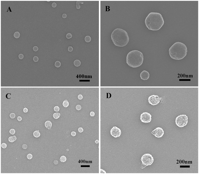 | ||
| Fig. 2 SEM images of Al-MOF with different magnification (A and B) and SEM images of RhB@Al-MOF with different magnification (C and D). | ||
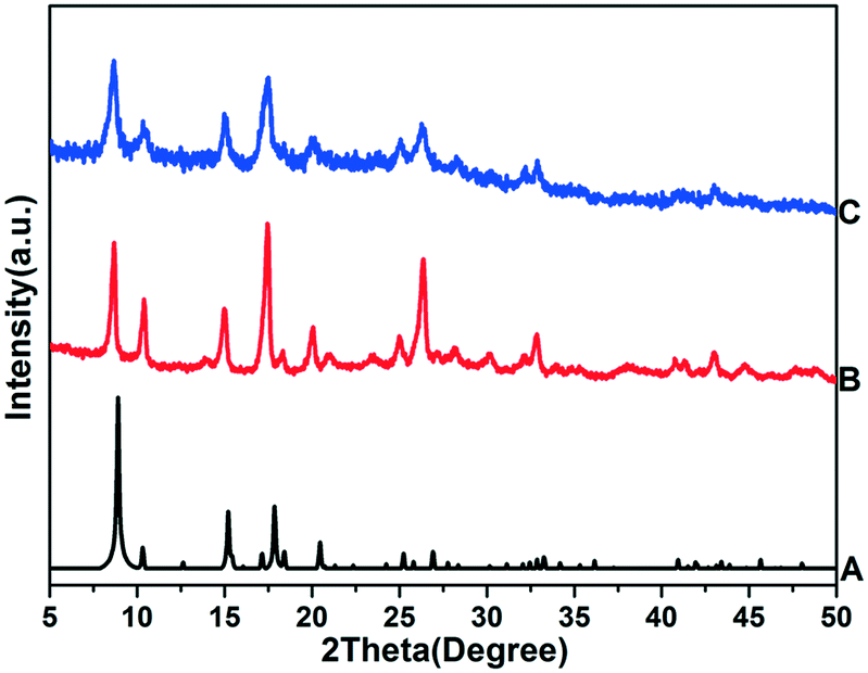 | ||
| Fig. 3 XRD patterns of simulated Al-MOF (A), as-prepared Al-MOF (B) and RhB@Al-MOF (C). | ||
Meanwhile, the generation of hierarchical pore during the encapsulation of RhB in the framework of RhB@Al-MOF is confirmed by the N2 adsorption–desorption isotherms shown in Fig. 4. The N2 sorption data of Al-MOF at 77 K displays a type IV isotherm which is typical for a mesoporous material while the N2 sorption data of RhB@Al-MOF displays a type I isotherm at relatively low P/P0 pressures and a typical type IV isotherm at relatively high P/P0, suggesting the presence of micropores and mesoporous in the RhB@Al-MOF nanomaterial. The diameter distribution is calculated using the Barrett–Joyner–Halenda (BJH) method and is shown in Fig. S3.† Apparently, pores with width 1.8 nm are present on the surface of Al-MOF. After loading RhB, the RhB@Al-MOF displays a broad range of pore diameters, around 1 nm, 1.3 nm, 1.4 nm, 2 nm, 3.8 nm and 10.5 nm, revealing that RhB can serve as a modulator to obtain hierarchical pores. Due to the hierarchical porous structures, the Brunauer–Emmett–Teller (BET) surface area of RhB@Al-MOF can reach to 231.8 m2 g−1 from 86.8 m2 g−1 of Al-MOF.
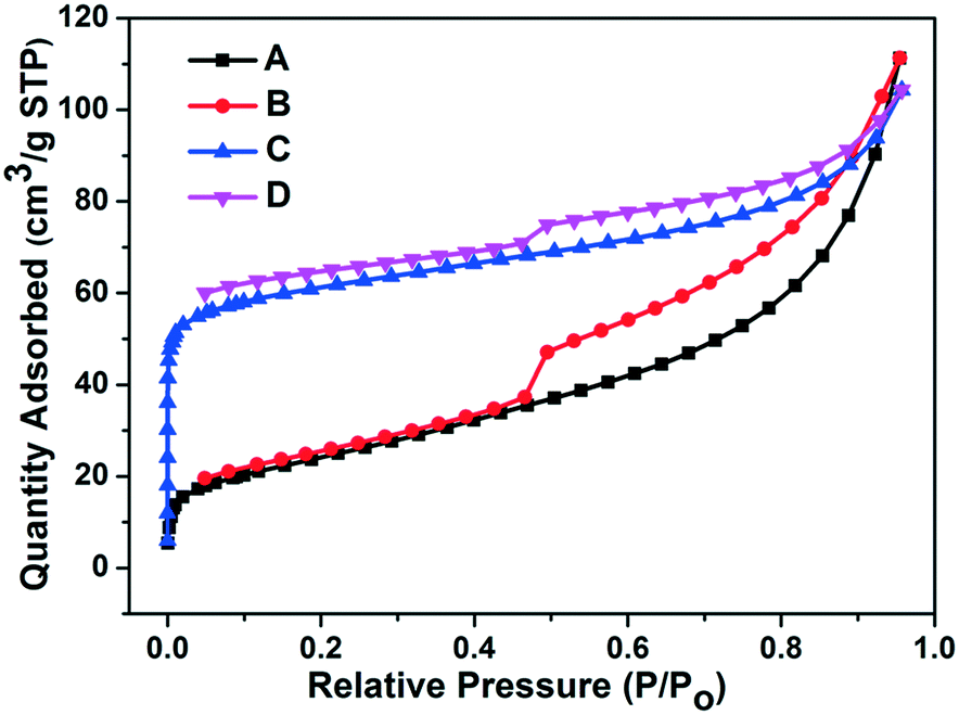 | ||
| Fig. 4 N2 adsorption (A) and desorption (B) isotherms of Al-MOF; N2 adsorption (C) and desorption (D) isotherms of RhB@Al-MOF. | ||
The FTIR spectra of the Al-MOF, RhB and RhB@Al-MOF are shown in Fig. S4.† As can be seen, in the FTIR spectra of pure Al-MOF and RhB, the absorption bands at 1590 cm−1 are associated with the vibrational bands of benzene. In the curve of RhB, the FTIR band at 1700 cm−1 can be assigned to the C![[double bond, length as m-dash]](https://www.rsc.org/images/entities/char_e001.gif) O stretching mode of COOH and the absorption band at 1067 cm−1 in the FTIR spectrum of Al-MOF can be attributed to the characteristics of Al–O vibrations. Nevertheless, in the FTIR spectrum of the RhB@Al-MOF, the characteristic peaks of the CO and Al–O are shifted to 1686 cm−1 and 1005 cm−1 respectively, indicating the strong interaction between COOH in RhB and Al3+ in Al-MOF. Meanwhile, this result also confirms the successful synthesis of RhB@Al-MOF.
O stretching mode of COOH and the absorption band at 1067 cm−1 in the FTIR spectrum of Al-MOF can be attributed to the characteristics of Al–O vibrations. Nevertheless, in the FTIR spectrum of the RhB@Al-MOF, the characteristic peaks of the CO and Al–O are shifted to 1686 cm−1 and 1005 cm−1 respectively, indicating the strong interaction between COOH in RhB and Al3+ in Al-MOF. Meanwhile, this result also confirms the successful synthesis of RhB@Al-MOF.
Additionally, the thermogravimetric analysis (TGA) shown in Fig. S5† further confirms this results. Al-MOF shows high thermal stability and the framework of Al-MOF begins to decompose when the temperature is higher than 400 °C (Fig. S5A†). However, RhB@Al-MOF exhibits weight loss when the temperature is above 100 °C because of decomposition of the loaded RhB (Fig. S5B†). Additionally, the loading efficiency of RhB on Al-MOF can be calculated for 10% according to the TGA curves.
Properties and applications of RhB@Al-MOF
The emission spectra of Al-MOF and RhB@Al-MOF are examined at room temperature in the solid state. As shown in Fig. 5, the free Al-MOF generates an intense and broad emission band with a maximum at 447 nm, while the emission spectrum of RhB@Al-MOF exhibits two emissions maxima at 458 nm and 610 nm under 375 nm, which is the optimal excitation peak of Al-MOF and RhB@Al-MOF shown in Fig. S6.† Clearly, RhB@Al-MOF shows the characteristic emission peaks of RhB (610 nm) and Al-MOF (458 nm). The emission at 458 nm is attributed to the Al-MOF, whereas the emission at 610 nm presumably originates from the dye RhB. Compared to the pure Al-MOF, the emission peak corresponding to Al-MOF in RhB@Al-MOF shifts to 450 nm, which is attributed to the strong interaction between RhB and Al-MOF. Additionally, we record the emission spectra of RhB under the same conditions in the solid state and RhB does not display any emission due to concentration quenching effects as shown in Fig. S7.† Meanwhile the solid-state UV-vis spectra (Fig. S8†) show that RhB@Al-MOF displays two distinct absorption peaks at 365 nm and 558 nm, which are assigned to Al-MOF and RhB, respectively. However, there is no absorption at 558 nm in the solid-state UV-vis spectra of RhB due to concentration quenching effects. These results demonstrate that the RhB is uniformly encapsulated in the framework of RhB@Al-MOF as a free isolated molecule, thus restraining the formation of aggregates or excimers in solid state dye materials.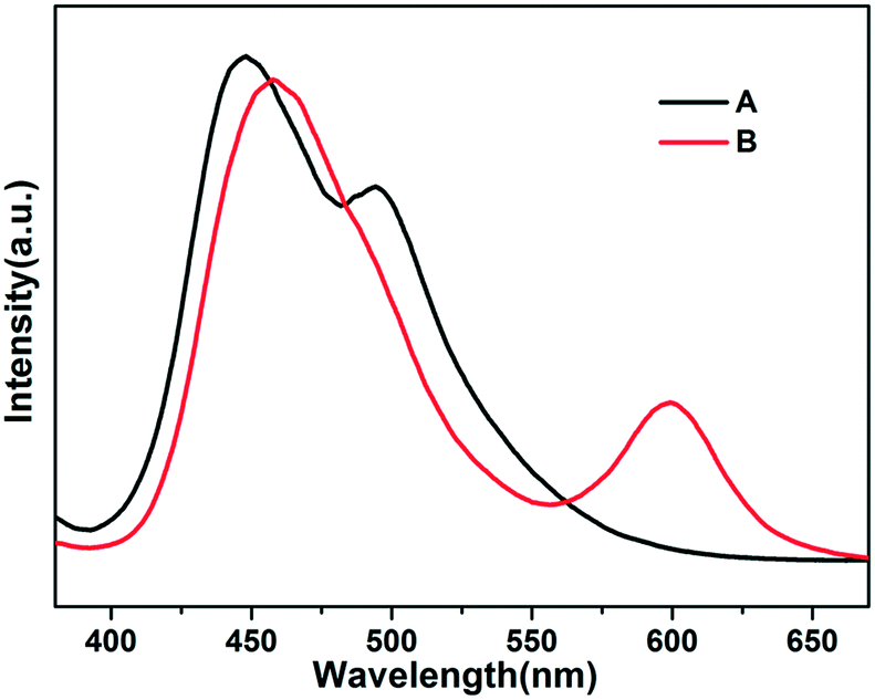 | ||
| Fig. 5 The emission spectra of Al-MOF (A) and RhB@Al-MOF (B) under 375 nm excitation in the solid state. | ||
Besides, the intense red fluorescence of RhB in the RhB@Al-MOF provides the possibility for fluorescence bioimaging due to the low background interference. Before testing the imaging ability of RhB@Al-MOF in cellular experiments, to ensure biocompatibility, the cell cytotoxicity of the RhB@Al-MOF with different concentrations is measured by standard MTT assay with HASMC normal cells and MGC-803 cancer cells. Apparently, the cell viability tests shown in Fig. 6 reveal that the cytotoxicity of RhB@Al-MOF to HASMC normal cells and MGC-803 cancer cells increases with increasing concentrations of RhB@Al-MOF and the cell survival rates of HASMC normal cells and MGC-803 cancer cells can reach 80% even at concentrations up to 200 μg mL−1, indicating the excellent biocompatibility of RhB@Al-MOF.
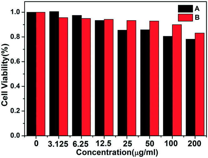 | ||
| Fig. 6 Viabilities of HASMC cells (A) and MGC-803 cells (B) in the presence of RhB@Al-MOF nanocomposite assayed by MTT. | ||
To confirm if the fluorescence signal also works in cells, cell imaging ability was investigated in vitro. As demonstrated in Fig. 7, there is an obvious fluorescence signal observed in the HASMC normal cells and the MGC-803 cancer cells after 4 hours of incubation. This phenomenon implies that the RhB@Al-MOF nanocomposites are able to enter into the cell and display strong red fluorescence. The biodistribution of the RhB@Al-MOF is crucial for their use as fluorescence imaging reagents in vivo; so this is studied by determining the fluorescence intensity in the major organs at 0 h, 12 h, 24 h time points post-injection. The tissue distribution of RhB@Al-MOF is expressed as the percentage of fluorescence intensity of the individual organs to the fluorescence intensity of total organs. According to the results shown in Fig. 8, it can be seen that RhB@Al-MOF is mainly accumulated in the liver, stomach, lung, kidney. This is to say, RhB@Al-MOF can transport to all tissues efficiently by blood transportation, which indicates great dispersibility and stability of RhB@Al-MOF for in vivo application.
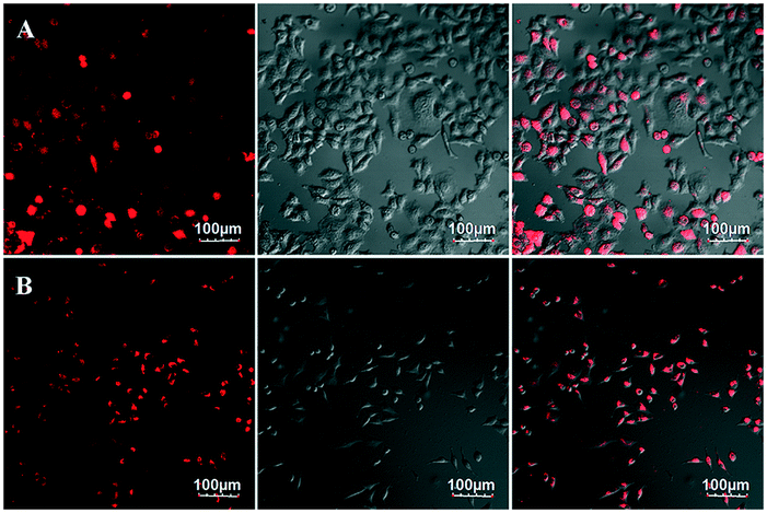 | ||
| Fig. 7 Fluorescence imaging of live MGC-803 cancer cells (A) and HASMC normal cells (B) after being incubated with RhB@Al-MOF nanomaterial for 4 h. The left panels show dark-field fluorescence images, the middle panels show the corresponding bright-field images and the right panels are overlays of the left and middle panels. Scale bar: 100 μm. | ||
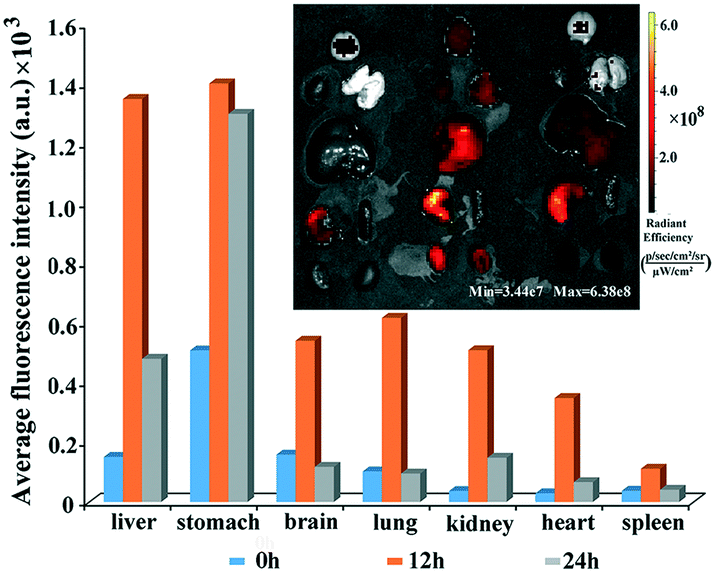 | ||
| Fig. 8 Biodistribution of RhB@Al-MOF in major organs excised from athymic nude mices after 24 h post-injection; ex vivo fluorescence imaging of different organs at 24 h time point post-injection (inset). | ||
Due to the hierarchical pore structure of RhB@Al-MOF, macromolecular drug TCH and small molecule drug 5-FU can be simultaneously loaded into the RhB@Al-MOF, which can be verified by the FTIR spectra shown in Fig. S9.† As can be seen, in the FTIR spectra of RhB@Al-MOF, the absorption band at 1005 cm−1 is associated with vibrational absorption of Al–O. In the FTIR spectra of 5-FU and TCH, the absorption bands at 1245 cm−1 and 1670 cm−1 are assigned to the vibrational bands of C–F and CO stretching mode of the CONH2. Additionally, the FTIR spectrum of RhB@Al-MOF/5-FU/TCH contains all the characteristic peaks of RhB@Al-MOF, 5-FU and TCH.
And drug loading does not affect the crystal structure of Al-MOF as shown in Fig. S10.† The drug loading efficiencies of 5-FU and TCH are thus reported as the m5-FU/mRhB@Al-MOF/5-FU/TCH and mTCH/mRhB@Al-MOF/5-FU/TCH. Meanwhile the drug loading efficiencies for TCH and 5-FU are 9% and 14%, respectively. The calibration curves of 5-FU and TCH are shown in Fig. S11.† To validate the sustained release properties of TCH and 5-FU, release experiments are carried out in PBS buffer solutions (pH = 7.4) at 37 °C. As Fig. 9 shows, the release rates of both TCH and 5-FU gradually decrease with time. The release of TCH and 5-FU can be divided into two phases: (1) gentle release phase attributed to the release of drug molecules adsorbed onto the surface of RhB@Al-MOF or in the entrance of the pore; (2) the slow release phase due to the extended diffusion route of TCH and 5-FU from the pores and cavities of RhB@Al-MOF to the surrounding environment. Due to the loading of TCH into larger pores, the release is easier and this release reaches a plateau within 15 h, while the slow release of 5-FU lasts for 30 hours.
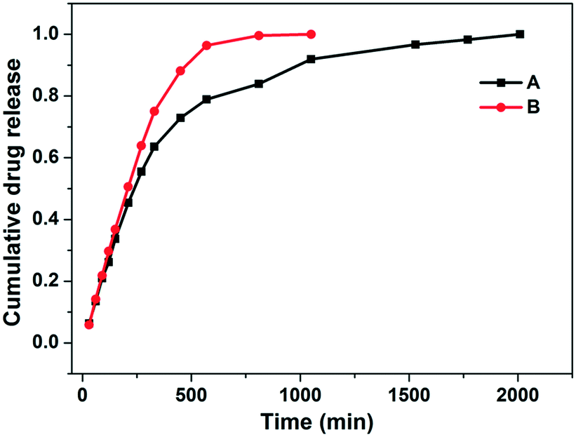 | ||
| Fig. 9 Drug release profiles of 5-FU (A) and TCH (B) from RhB@Al-MOF/5-FU/TCH in PBS buffer solution at pH = 7.4. | ||
Additionally, the XRD pattern of RhB@Al-MOF/5-FU/TCH after drug release shows strong diffraction peaks that agree well with the original RhB@Al-MOF/5-FU/TCH (Fig. S12†), suggesting that RhB@Al-MOF is stable under physiological conditions and can be used as an ideal drug carrier. These results clearly show that RhB@Al-MOF exhibits satisfactory drug loading capacity and excellent time-release properties for both TCH and 5-FU, making its presence known in the area of drug delivery.
Conclusions
In summary, H-MOF with a designable encapsulating functional species RhB has been successfully synthesized by a one-step method. It is found that the introduction of RhB into Al-MOF is essential for the creating a hierarchical-pore structure because RhB can form weak coordination bonds with Al3+ ions and modulate the formation of the hierarchical pore during the encapsulation of the RhB. Due to uniform encapsulation in the framework of RhB@Al-MOF as free isolated molecules, RhB still shows strong red fluorescence and can realize high quantum yield and low-background fluorescence imaging in vivo. Meanwhile the existence of the hierarchical-pore makes the obtained H-MOF display excellent drug loading and releasing behaviors for both macromolecular drug TCH and small molecule drug 5-FU. In summary, a simple, one-pot process has been developed for the synthesis of H-MOF with excellent drug loading behavior and excellent fluorescence imaging capacity. This efficient, low cost and scalable method provides new opportunities to develop multifunctional materials based on MOFs for application in extensive drug delivery and fluorescence imaging.Conflicts of interest
The authors report no conflicts of interests.Acknowledgements
This work was supported by the Natural Science Foundation of China (21361016 and 21761023) and the Inner Mongolia Autonomous Region Fund for Natural Science (2017ZD01).References
- A. C. McKinlay, R. E. Morris, P. Horcajada, G. Ferey, R. Gref, P. Couvreur and C. Serre, Angew. Chem., Int. Ed., 2010, 49, 6260–6266 CrossRef CAS PubMed
.
- J. Della Rocca, D. Liu and W. Lin, Acc. Chem. Res., 2011, 44, 957–968 CrossRef CAS PubMed
- P. Horcajada, R. Gref, T. Baati, P. K. Allan, G. Maurin, P. Couvreur, G. Férey, R. E. Morris and C. Serre, Chem. Rev., 2012, 112, 1232–1268 CrossRef CAS PubMed
- D. Cunha, M. B. Yahia, S. Hall, S. R. Miller, H. Chevreau, E. Elkaïm, G. Maurin, P. Horcajada and C. Serre, Chem. Mater., 2013, 25, 2767–2776 CrossRef CAS
- X. G. Wang, Z. Y. Dong, H. Cheng, S. S. Wan, W. H. Chen, M. Z. Zou, J. W. Huo, H. X. Deng and X. Z. Zhang, Nanoscale, 2015, 7, 16061–16070 RSC
- M. Nazari, M. Rubio-Martinez, G. Tobias, J. P. Barrio, R. Babarao, F. Nazari, K. Konstas, B. W. Muir, S. F. Collins, A. J. Hill, M. C. Duke and M. R. Hill, Adv. Funct. Mater., 2016, 26, 3244–3249 CrossRef CAS
- L. Cooper, T. Hidalgo, M. Gorman, T. Lozano-Fernandez, R. Simon-Vazquez, C. Olivier, N. Guillou, C. Serre, C. Martineau and F. Taulelle, Chem. Commun., 2015, 51, 5848–5851 RSC
- C. Wang, D. Liu and W. Lin, J. Am. Chem. Soc., 2013, 135, 13222–13234 CrossRef CAS PubMed
- R. Lyndon, K. Konstas, A. W. Thornton, A. J. Seeber, B. P. Ladewig and M. R. Hill, Chem. Mater., 2015, 27, 7882–7888 CrossRef CAS
- P. Horcajada, C. Serre, M. Vallet-Regí, M. Sebban, F. Taulelle and G. Férey, Angew. Chem., Int. Ed., 2006, 45, 5974–5978 CrossRef CAS PubMed
- P. Horcajada, T. Chalati, C. Serre, B. Gillet, C. Sebrie, T. Baati, J. F. Eubank, D. Heurtaux, P. Clayette and C. Kreuz, Nat. Mater., 2010, 9, 172–178 CrossRef CAS PubMed
- J. Della Rocca, D. Liu and W. B. Lin, Acc. Chem. Res., 2011, 44, 957–968 CrossRef CAS PubMed
- P. P. Bag, D. Wang, Z. Chen and R. Cao, Chem. Commun., 2016, 52, 3669–3672 RSC
- D. Cunha, C. Gaudin, I. Colinet, P. Horcajada, G. Maurin and C. Serre, J. Mater. Chem. B, 2013, 1, 1101–1108 RSC
- X. S. Meng, B. Gui, D. Q. Yuan, M. Zeller and C. Wang, Sci. Adv., 2016, 2, e1600480 Search PubMed
- S. He, Y. F. Chen, Z. C. Zhang, B. Ni, W. He and X. Wang, Chem. Sci., 2016, 7, 7101–7105 RSC
- X. Du, C. X. Zhao, M. Y. Zhou, T. Y. Ma, H. W. Huang, M. Jaroniec, X. J. Zhang and S. Z. Qiao, Small, 2017, 13, 1602592 CrossRef PubMed
- Y. Wei, T. E. Parmentier, K. P. de Jong and J. Zečević, Chem. Soc. Rev., 2015, 44, 7234–7261 RSC
- S. Dutta, K. C. W. Wu and T. Kimura, Chem. Mater., 2015, 27, 6918–6928 CrossRef CAS
- Y. Wan and D. Zhao, Chem. Rev., 2007, 107, 2821–2860 CrossRef CAS PubMed
- L. Qiu, G. T. Xu, Z. Q. Li, W. Wang, Y. Wu, X. Jiang, X. Y. Tian and L. D. Zhang, Angew. Chem., Int. Ed., 2008, 47, 9487–9491 CrossRef CAS PubMed
- D. Bradshaw, S. El-Hankari and L. Lupica-Spagnolo, Chem. Soc. Rev., 2014, 43, 5431–5443 RSC
- T. Lu, L. C. Zhang, M. X. Sun, D. Y. Deng, Y. Y. Su and Y. Lv, Anal. Chem., 2016, 88, 3413–3420 CrossRef CAS PubMed
- T. J. Sun, X. Y. Ren, J. L. Hu and S. D. Wang, J. Phys. Chem. C, 2014, 118, 15630–15639 CAS
- B. J. Liu, F. Yang, Y. X. Zhou and Y. Peng, J. Chem. Eng. Data, 2014, 59, 1476–1482 CrossRef CAS
- B. M. Estevão, I. Miletto, L. Marchesea and E. Gianottia, Phys. Chem. Chem. Phys., 2016, 18, 9042–9052 RSC
- M. Beija, C. A. M. Afonso and J. M. G. Martinho, Chem. Soc. Rev., 2009, 38, 2410–2433 RSC
- X. L. Hu, C. Qin, X. L. Wang, K. Z. Shao and Z. M. Su, Chem. Commun., 2015, 51, 17521–17524 RSC
- M. S. T. Gonalves, Chem. Rev., 2009, 109, 190–212 CrossRef PubMed
- L. Mojardin, J. Botet, L. Quintales, S. Moreno and M. Salas, PLoS One, 2013, 8, e78172 CAS
- M. E. El-Naggar, A. M. Abdelgawad, C. Salas and O. J. Rojas, Carbohydr. Polym., 2016, 154, 194–203 CrossRef CAS PubMed
- S. Couck, J. F. M. Denayer, G. V. Baron, T. Rémy, J. Gascon and F. Kapteijn, J. Am. Chem. Soc., 2009, 131, 6326–6327 CrossRef CAS PubMed
- S. Couck, T. Rémy, G. V. Baron, J. Gascon, F. Kapteijn and J. F. M. Denayer, Phys. Chem. Chem. Phys., 2010, 12, 9413–9418 RSC
Footnotes |
| † Electronic supplementary information (ESI) available: Chemical structures, SEM images, pore size distribution, FTIR spectra, TGA cures, fluorescence spectra, XRD patterns and the calibration curves are obtained in supporting information. Supplementary data to this article can be found online. See DOI: 10.1039/c7ce02053h |
| ‡ These authors contributed equally to this work. |
| This journal is © The Royal Society of Chemistry 2018 |