DOI:
10.1039/C6CE02490D
(Paper)
CrystEngComm, 2017,
19, 1470-1478
HKUST-1 coatings on laser-microperforated brass supports for water adsorption†
Received
1st December 2016
, Accepted 10th January 2017
First published on 10th January 2017
Abstract
This work describes the preparation of HKUST-1 layers on brass supports by a thermal gradient approach. Supports were perforated using laser irradiation to create 30–50 μm microholes. Perforation improved the adhesion and loading of the MOF. The microhole environment generated during the laser treatment led to well-anchored coatings. Two distinct samples were synthesized with the reaction temperature (100 and 150 °C) as the main difference. A continuous HKUST-1 coating was only achieved with the higher temperature of 150 °C. However, the microholes were totally filled with crystals in both samples reaching weight fractions of crystallized material of 2.4 and 6.6 wt%. PXRD and N2 physisorption studies confirmed the formation of HKUST-1 crystals with high quality (SBET = 1105 m2 g−1). Water adsorption was performed on both samples, showing the main sorption event below a relative pressure of 0.4 and obtaining uptakes (0.48 and 0.45 g g−1 at 293 K and p/p0 = 0.9) among the reported values for HKUST-1 powder. The HKUST-1 properties and the enhanced MOF–support interaction make these coatings candidates for use in gas storage and separation, sensing and water-based adsorption applications, such as chillers or heat pumps.
Introduction
The global warming phenomenon has attracted much attention in recent years. Many efforts are aimed at mitigating the effects of anthropogenic actions of emitting and distorting the presence of greenhouse gases in the atmosphere. In particular, the contribution of chlorofluorocarbon (CFC) and hydrochlorofluorocarbon (HCFC) gases to climate change is estimated to be roughly 12% of the total impact from greenhouse gases.1 In addition, stratospheric accumulation of CFCs and HCFCs, having long atmospheric lifetimes, causes ozone layer depletion.1 Environmental concerns about the use of CFCs and HCFCs as refrigerants have provoked the search for harmless working fluids.2 Adsorption technology employs more environmentally friendly refrigerants such as water, ammonia, methanol and ethanol.3,4 Despite the problems arising from its low vapour pressure, water is the preferable refrigerant owing to its non-toxicity and high latent heat of vaporization.3,5,6 Adsorption cycle systems can operate using efficient energy resources, such as waste heat and solar energy.3,7 Active carbons, silica gels and zeolites are the adsorbents usually employed.3 Recent studies have focused on metal–organic frameworks (MOFs) as adsorbents for efficient sorption-based heating and cooling systems with water as the refrigerant.8–17 The increasing interest in MOFs as water adsorbents is due to the wide variety of available organic and inorganic moieties affording tunable pore sizes, shapes and chemical surfaces, thus tailoring their adsorption and chemical properties.14,17–21 MOFs, also known as porous coordination polymers (PCPs), are highly porous compounds consisting of metal ions or clusters coordinated by organic linkers leading to one-, two- or three-dimensional networks.22 MOFs have emerged as intriguing materials for a number of applications, such as catalysis,23,24 encapsulation,25 gas separation26 and storage,23,27 drug delivery,23 sensor technology,28etc.
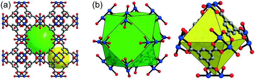
HKUST-1 (also named Cu-BTC or MOF-199, [Cu3(BTC)2(H2O)3]n) is a MOF with an open framework composed of Cu2+ cations as metal nodes and benzene-1,3,5-tricarboxylate (BTC) anions as organic connectors.29 The pseudo-octahedral coordination sphere of HKUST-1 includes paddle-wheel clusters formed by dinuclear cupric tetracarboxylate units (Cu2(OOC–)4).29–31 Cu2+ ions are coordinated by four oxygen atoms from BTC and one oxygen atom in the axial position from a water ligand.29 HKUST-1 comprises two kinds of pores and windows. Larger cuboctahedral pores (11 Å), delimited by 12 paddle-wheel subunits, are accessible through square-shaped windows (9 Å) (Fig. 1).29,32,33 Octahedral side cavities (5 Å) are connected to the main channels by triangular windows (3.5 Å) (see also Fig. 1).32–34 The inner surface of the smaller pockets comprises four benzene rings from BTC resulting in a more hydrophobic character.35 Upon activation, water ligands are removed from the HKUST-1 structure creating coordinatively unsaturated metal sites (CUS).30 Thereby, coordinative vacancies on Cu2+ cations could bind to distinct guests, such as water molecules, among others.36
 |
| | Fig. 1 (a) Representation of the bimodal pore system of HKUST-1 viewed along the (1 0 0) direction. Green and yellow spheres are depicted filling the larger cuboctahedral (11 Å) and smaller octahedral cavities (5 Å). (b) Details of the cuboctahedral (left) and octahedral (right) pores. Cu, O and C atoms are coloured in blue, red and grey, respectively. H atoms are omitted for clarity. | |
In this work, HKUST-1 layers were prepared on microperforated brass supports following a thermal gradient synthesis.37 The thermal gradient synthesis allows better control of MOF deposition on the supports38 and renders mechanically and thermally stable coatings.37–39 Perforations of metal substrates were carried out by laser irradiation to promote the formation of HKUST-1. For many years, laser technology has been widely applied in common metal drilling and machining processes.40,41 But laser processing has also been used in the so-called surface activation and surface engineering for numerous purposes. For instance, laser surface engineering afforded the development of controllable wettability on distinct materials42 and preservation of functional properties under abrasive wear and cavitation loads.43 In addition, chemical surface activation enhanced the biocompatibility in implants and controlled the cell growth,44,45 as well as improved the bonding in metal–ceramic joints.46 Previously in our group, laser microperforation was used to activate silicalite-1 and ZIF-8 growth on stainless steel47 and brass sheets,48 respectively, for micromembrane preparation. In this case, the process also profited from the chemical surface activation of brass due to the melting and spallation phenomena related to laser ablation during the drilling process. Therefore, two distinct HKUST-1–brass samples were synthesized by changing the reaction temperature to form a uniform HKUST-1 layer on the laser-perforated support. Characterization by different techniques (optical microscopy, OM; scanning electron microscopy, SEM; energy-dispersive X-ray spectroscopy, EDX; powder X-ray diffraction, PXRD; N2 physisorption) and water sorption isotherms of both samples are presented and discussed. Upon demonstration of adsorbate access to the microporosity of the MOF present in the MOF–metal composite, supporting HKUST-1 on microperforated metal sheets could provide advantages in adsorption-based applications taking into account the MOF properties along with the water sorption uptakes in accordance with values from the bulk powder. The highly porous coatings obtained in this work could increase the efficiency of adsorption systems by reducing the heat and mass transfer limitations.38
Experimental section
General methods and materials
Copper(II) nitrate hemi(pentahydrate) (Cu(NO3)2·2.5H2O, >99.99%, Aldrich), benzene-1,3,5-tricarboxylic acid (H3BTC, C6H3(CO2H)3, 98%, Alfa Aesar), and N,N-dimethylformamide (DMF, HCON(CH3)2, 99.99%, Fisher Chemical) were obtained commercially and used without further purification.
Perforation of brass supports
The laser used was a commercial diode-pumped Yb:YAG fiber laser device emitting at 1050 nm (Easy Mark 20, Jeanologia) with a 100 ns pulse width and the beam was deflected by a pair of galvanometric mirrors controlled by CAD software. The laser CAD software allows generating a predefined pattern of spots onto a given material surface with any geometrical design by combining the laser repetition rate and the scanning speed. The pattern may be repeated as many times as required assuring exactly coincidence in position so that, in principle, sheets of any thickness can be drilled by just varying the number of laser cycles. In this case, brass sheets of 75 μm thickness were drilled with a 4 kHz repetition rate and a 500 mm s−1 scanning speed that yielded a pattern of holes with 125 μm of separation between centres. For this sheet thickness, 50 cycles were needed to complete drilling the material. The energy parameter applied was 150 J cm−2. According to energy-dispersive X-ray spectroscopy, brass sheets were composed of 68, 30 and 2 atomic% Cu, Zn and O, respectively, thus the Cu/Zn ratio was 2.3. Square sheets, 5 × 5 cm2, were employed and irradiated generating a dot linear pattern of 4.5 × 4.5 cm2.
Synthesis of HKUST-1 coatings on microperforated brass sheets
After perforation, supports were washed twice with water and acetone for 15 min in an ultrasonic bath to remove impurities. The supports were dried at 100 °C overnight. HKUST-1 was formed on the perforated brass supports by means of the thermal gradient approach reported by Jeremias et al.37 and following their synthesis conditions. Sample 1 and sample 2 were prepared from a solution of 8.17 g of Cu(NO3)2·2.5H2O and 4.21 g of H3BTC in 250 mL of DMF. The synthesis was carried out using a heating block (Fig. S1a†). The heating block consists of a rectangular prism made of brass. The block has 6 bores: one for mounting purposes, one for temperature control by a thermocouple and four for insertion of the heating cartridges. The support was grabbed with clips on the heating block in such a way that its non-irradiated side was in contact with the block surface and not with the solution. Consequently, crystals were only formed on the irradiated surface of the substrate. The block with the brass sheet attached was placed into the reactant solution. The glass beaker containing the solution and the heating block was immersed in a cooling thermostatic bath (Fig. S1b†). The temperatures on the block surface and near the beaker wall (at the interface between the cooling bath and the synthesis solution) were continuously monitored. The heating power was adjusted in such a way that the surface temperature was 100 and 150 °C for sample 1 and sample 2. The temperature of the cooling bath was set at 10 and 75 °C for sample 1 and sample 2, respectively. After a reaction time of 2 h, the setup was cooled down to room temperature. Blue HKUST-1 crystals covered the perforated sheets. The sheets were rinsed twice with DMF and dried under ambient conditions. Table S1† shows the synthesis parameters and MOF weight fractions of both sample 1 and sample 2.
Characterization
Optical microscopy (OM) images were taken with a Leica M80 reflected-light microscope. Powder X-ray diffraction (PXRD) patterns were obtained at ambient temperature on a Bruker D2 Phaser equipped with a Lynx-Eye detector in reflection geometry. Samples for PXRD were prepared on a flat sample holder with a Si-wafer platform using Cu-Kα radiation (λ = 1.54182 Å). Molecular graphics of HKUST-1 were obtained with Diamond49 using the cif file from Yakovenko et al. (CCDC 943009).50 Scanning electron microscopy (SEM) images were recorded with a Jeol JSM-6510LV QSEM advanced electron microscope with a LAB-6 cathode at 5–20 keV. The microscope was equipped with a Bruker XFlash 410 silicon drift detector and Bruker ESPRIT software for energy-dispersive X-ray spectroscopy (EDX) analysis. Cu, Zn, C and O atomic composition maps were obtained by EDX. Atomic percentages were calculated as an average of measurements on two distinct spots. Cross-sections were prepared by cutting the samples with conventional scissors along the perforation of the support and then coated with gold by a Jeol JFC 1200 fine-coater (at an approximate current of 20 mA for 20–30 s). N2 physisorption isotherms were acquired on a Nova 4000e from Quantachrome at 77 K. Brunauer–Emmett–Teller (BET) surface areas were calculated from the N2 sorption isotherms. Water physisorption isotherms were measured volumetrically on a Quantachrome Autosorb iQ MP at 293 K. For measuring the isotherms, samples were loaded into glass tubes capped with septa. The weighed tubes were attached to the corresponding degassing port of the sorption analyzer, degassed under vacuum at 160 °C for 2 h, weighed again and then transferred to the analysis port of the sorption analyzer. The adsorption phenomenon is only due to the MOF because the metal substrate does not show sorption features. For this reason, the N2 and water isotherms were corrected by dividing the adsorption data by the MOF weight fraction of the corresponding sample.
Results and discussion
Microperforated brass sheets
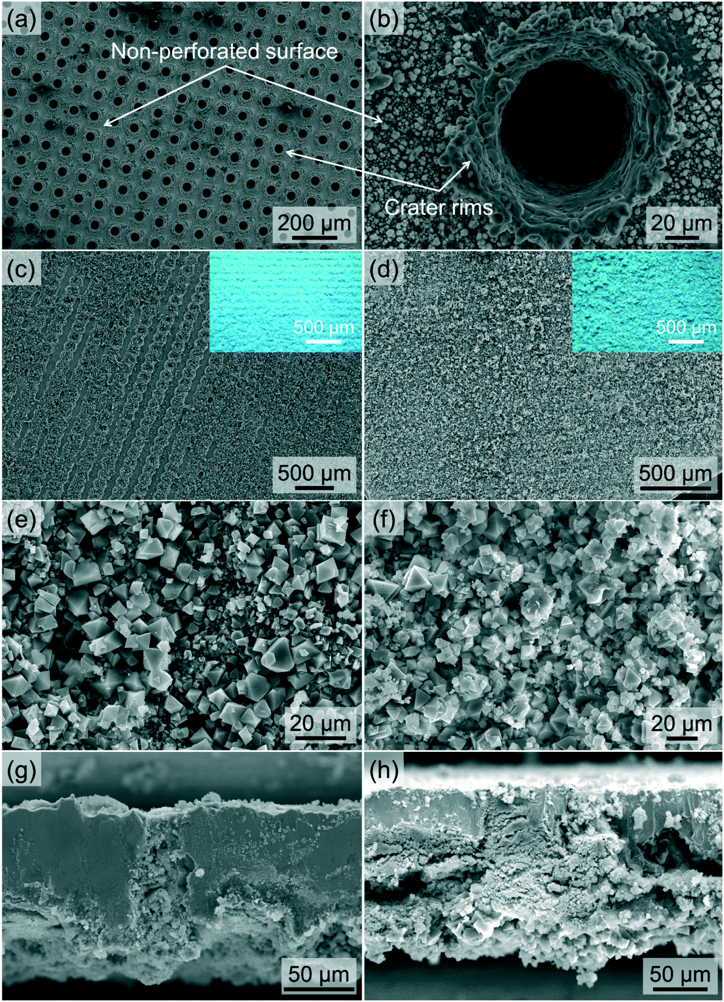
The goals of using laser irradiation to perforate brass sheets were to achieve a high (through the filling of the support microperforations) and uniform loading of MOF material and to improve the MOF–support attachment through the created roughness. Laser irradiation produced truncated cone-shaped holes with the largest and smallest diameters of ca. 50 and 30 μm, respectively. The higher diameter corresponds to the irradiated side of the support. On this side, the surface became rough and craters appeared around holes (Fig. 2a and b). EDX analysis at the area between holes gave an atomic composition of 31, 32 and 37% Cu, Zn and O, respectively (see Table S2†). However, these values were 49, 35 and 16% at the crater rims. The resulting atomic Cu/Zn ratios, therefore, decreased to 1.0 and 1.4 for the non-perforated surface and crater rims, respectively, in comparison with the value from the bare metal sheet (2.3). According to the work reported by Navarro et al., one could expect an increment instead of a reduction in the ratio of the laser-affected zones due to higher volatilization of Zn (lower vaporization temperature), giving rise to Cu enrichment.48 In our case and probably due to a smaller diameter of the inlet microperforations (50 μm vs. 72 and 59 μm for Navarro et al.48), after laser ablation, Zn recondensed and was deposited on the surface between craters. The evaporated material inside the holes was unable to leave the craters and was deposited on the hole walls and crater peripheries.51 Both facts resulted in Zn enrichment in the non-perforated areas and crater rims, as compared to the bare sheet, decreasing the Cu/Zn ratio. On the other hand, the atomic content of O was moderately raised from 2 to 16% for the crater rims while it was substantially increased from 2 to 37% for the surface between holes, so the metallic oxides were preferentially formed at the non-irradiated zones, more exposed to the surrounding atmosphere. As seen in Fig. 2b, the non-perforated areas are partially covered with particles deposited during irradiation as a result of the ablation and oxidation of the brass sheet. Smaller particles are generated by nucleation and condensation of vapour and are placed away from craters.51,52 Bigger particles are ejected from the melted liquid remaining at the craters' surroundings.51,52 Several authors have related the particle size with the composition, determining that the larger particles are mainly composed of Cu, whereas the smaller particles are rich in Zn.52,53 Liu et al.52 supported that vaporized atoms and ions condense on the ejected droplets creating an outer layer. Thus, vaporized Zn is supposed to condense as ZnO, forming small particles and covering large ejected Cu droplets. The lower standard reduction potential of Zn in comparison to that of Cu facilitates the formation of ZnO instead of CuO. Although HKUST-1 is not constituted by Zn, ZnO could affect and assist the formation of the MOF acting as heterogeneous nucleation sites.54 On the other hand, the higher content of Cu species in the crater rims may facilitate the growth of HKUST-1 crystals on them.
 |
| | Fig. 2 Top view SEM images of (a) linear patterns and (b) a microhole detail from the laser-irradiated side of the brass support, (c and e) sample 1 and (d and f) sample 2. Insets in images (c) and (d) are the corresponding optical images. Cross-sectional SEM images of (g) sample 1 and (h) sample 2. | |
Characterization of HKUST-1 coatings on microperforated brass supports
The thermal gradient approach was developed by Jeremias and co-workers in 2012.37 They used the thermal gradient synthesis to grow a dense HKUST-1 layer on a copper substrate. Conductivity tests were carried out, determining good heat transfer between the MOF and the metallic sheet. A similar procedure was reported by Tatlier and Erdem-Senatalar in 1999.38 They prepared zeolite 4A coatings on stainless steel substrates to enhance the mass and heat transfer in adsorption heat pumps. Here, HKUST-1 coatings were synthesized on laser-microperforated brass supports instead of bare substrates to improve the MOF–metal interaction, as mentioned above, and water sorption studies were carried out (see below). HKUST-1 was selected as the adsorbent because it is one of the most investigated hydrophilic MOFs, thus its properties such as thermal and chemical stabilities and high surface area are well-known. Concerning its water vapour stability, Low et al.55 placed HKUST-1 in the moderate steam stability region. In contrast, the studies of Küsgens et al.35 and Henninger et al.9 concluded that this MOF degrades upon vapour exposure and under hydrothermal conditions, respectively.
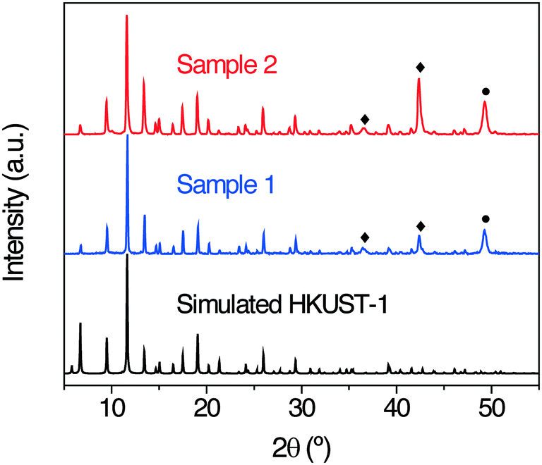
Sample 1 and sample 2 were prepared following conditions similar to those used by Jeremias et al.,37 but the heating block surface (100 and 150 °C) and cooling bath (10 and 75 °C) temperatures were different (Table S1†). As a result, sample 1 achieved a 2.4 wt% MOF loading, whereas sample 2 achieved a 6.6 wt% MOF loading. The increase in the block surface temperature for sample 2 led to a higher reaction rate, resulting in the formation of more MOF material. OM images reveal that both sheets were completely coated with blue crystals (see insets in Fig. 2). The PXRD patterns of sample 1 and sample 2 are in good agreement with the simulated pattern of HKUST-1,50 confirming that the blue crystals were HKUST-1 (Fig. 3). No peaks related to ZnO or CuO are observable. In contrast, contributions of Cu2O and a rouaite phase from Cu2NO3(OH)3 are present (denoted in Fig. 3 by black rhombi and circles), as reported in the article by Jeremias et al.37 Sample 1 is mostly composed of HKUST-1, with only weak intensities coming from the abovementioned impurities. On the other hand, the stronger intensities of peaks in sample 2 related to Cu2O and rouaite phases denote a higher content of impurities. Sample 1 was not uniformly coated with MOF crystals, as observed in Fig. 2c. HKUST-1 principally adhered to the rough edges and not to the non-perforated surface. Thus, MOF formation was benefited from a larger amount of Cu on crater rims and the creation of roughness in spite of the higher presence of metallic oxides on the surface between holes. Unlike sample 1, sample 2 was completely covered by crystals (Fig. 2d), thus the higher temperature synthesis favoured the formation of a continuous coating. Microholes were blocked with crystals for both samples (Fig. 2g and h). The crystals exhibit an octahedral shape typical for HKUST-1 (Fig. 2e and f). The crystal size distribution for both samples is heterogeneous with sizes ranging from 1 to 15 μm and from 2 to 30 μm for sample 1 and sample 2, respectively. The thicknesses of the HKUST-1 layers are about 26 for sample 1 and 42 μm for sample 2, as seen in Fig. 4. The larger size of the crystals and layer thickness in sample 2 are due to the higher reaction temperature of 150 °C used in its synthesis. The existence of Zn deposits on the brass substrates after laser irradiation could have brought about the appearance of Zn–HKUST-1, a polymorph of HKUST-1 with Zn2+ as the metal cation.56,57 However, Zn–HKUST-1 crystals are colourless and cubic. If the Zn analogue had been formed in large amounts, its presence would have been identified through SEM, PXRD and OM characterization.
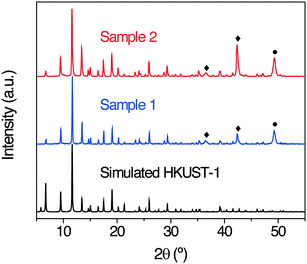 |
| | Fig. 3 PXRD patterns of sample 1 and sample 2 in comparison with that of simulated HKUST-1 (CCDC 943009).50 Symbols denote peaks assignable to: ♦, Cu2O and ●, rouaite Cu2NO3(OH)3. | |
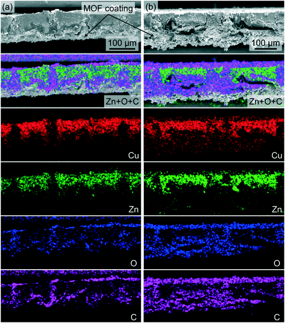 |
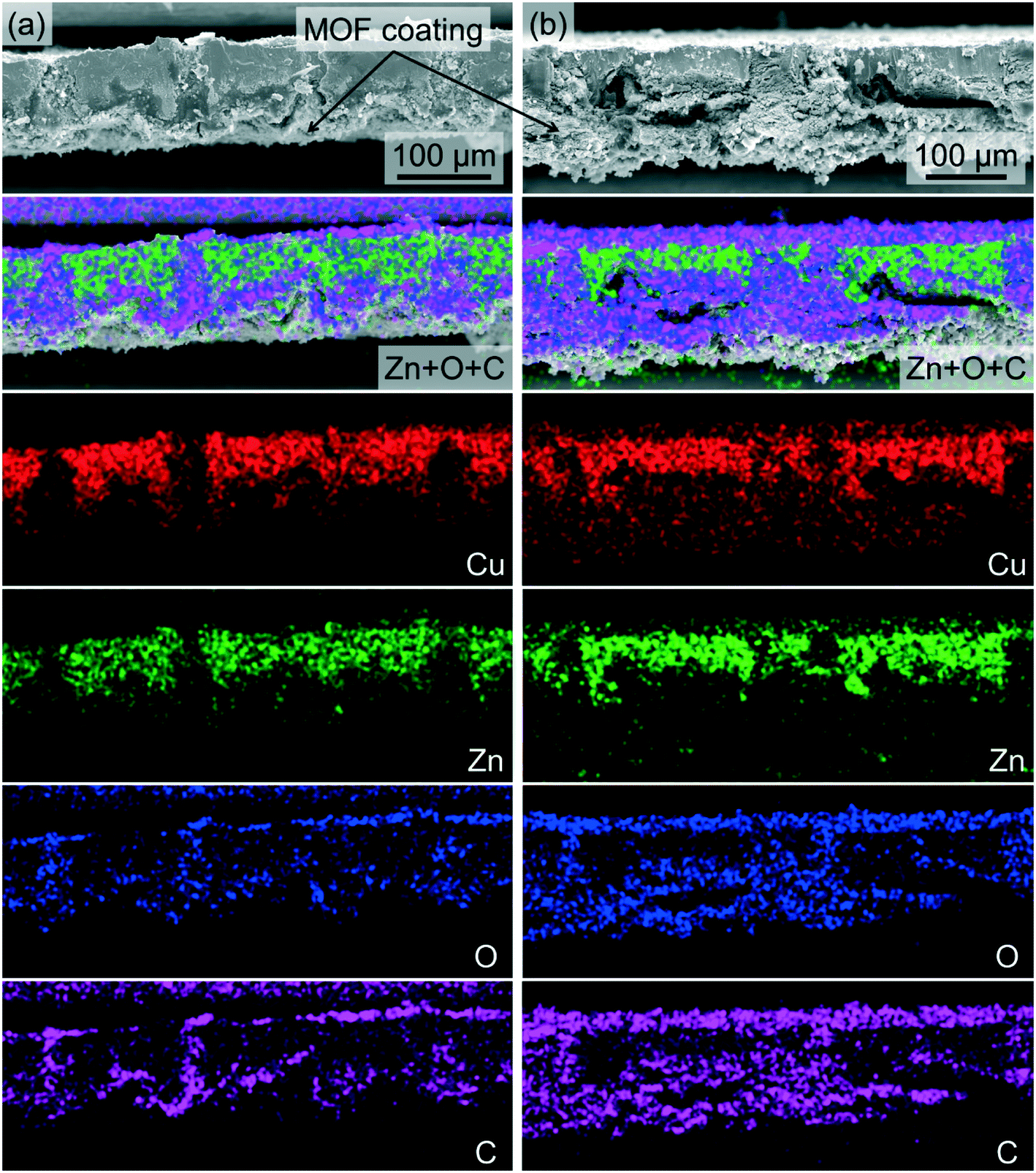
| | Fig. 4 Cross-sectional EDX mapping images of (a) sample 1 and (b) sample 2. Cu, Zn, O and C are represented in red, green, blue and pink, respectively. The laser-irradiated sides of the supports are facing down. In the Zn + C + O-overlaid images (second row from the top), Cu has been omitted for better contrast as it is part of both HKUST-1 and the perforated brass support. The crystalline non-coloured part of the sample at the bottom of the layered image is the surface of the MOF layer which is not part of the elemental map because it is located in a further distance from the electron beam compared to the cross-section of the sample. Zn and Cu are also detected outside the sample cross-sections because the sample holder is made from brass. | |
EDX analysis was performed on the cross-sections of both samples in order to visualize the deposition of the MOF (Fig. 4). The different elemental mappings show areas where the Cu and Zn concentrations are higher corresponding to the brass support while higher O and C concentrations indicate the MOF. In the Zn + O + C-overlaid images, the thorough hole-filling is clearly visualized. Some MOF crystals were also deposited on the laser-irradiated side of the support, where the C and O density is higher. The N2 physisorption isotherm at 77 K of sample 2 and its corresponding correction using the MOF weight fraction are displayed in Fig. S2.† As the metal substrate does not exhibit any adsorption, isotherm data were divided by the actual MOF weight fraction (wt%) to correct the uptake values, referencing them to the amount of MOF. The N2 isotherms are a combination of types I and IV, typical for microporous and mesoporous materials. This implies the presence of hierarchical porosity,58 with some mesoporosity coming from intercrystalline voids, in accordance with a thin hysteresis loop from p/p0 = 0.4. The BET specific surface area for the corrected sample 2 (1105 m2 g−1) is found among the values reported in the literature for HKUST-1 powder (Table S3†). This is consistent with the formation of high-quality MOF crystals.
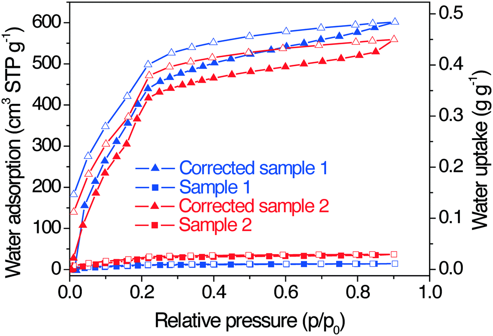
Water adsorption of HKUST-1 coatings
Water adsorption was carried out on sample 1 and sample 2 at 293 K. Besides the adsorption data for the composite sample, isotherms obtained through the correction with the MOF weight percent are also depicted in Fig. 5. Water adsorption occurs in a two-step fashion. According to the work developed by Küsgens et al.,35 the first step (p/p0 = 0.04–0.16) corresponds to the filling of more hydrophilic (cuboctahedral, 11 Å) pores via interaction of water with CUS. The second step (p/p0 = 0.16–0.4) is related to either total filling of cuboctahedral pores or filling of less hydrophilic (octahedral, 5 Å) cages.35 Water adsorption on HKUST-1 pores is a controversial issue since it has also been suggested that the filling of water could take place first on the octahedral micropores with the consecutive adsorption on the cuboctahedral cavities.59 The slight increase in adsorption above p/p0 = 0.8 indicates water condensation in voids between MOF particles.35 Hysteresis is promoted due to the strong hydrogen bonds between water molecules.35 Furthermore, the chemisorption of water molecules by copper sites caused an open hysteresis loop, denoting an irreversible process.35 It is worth mentioning that the adsorption phenomenon takes place mainly at a low relative pressure range, being of great interest for thermally driven chillers or adsorption-based heat pumps, where the working relative pressure region is p/p0 = 0.05–0.32.17 When comparing water adsorption capacities with HKUST-1 powder data from other studies (Table 1), the corrected uptakes for sample 1 and sample 2 (at 293 K) are observed within the range of the reported values (at 298 K). Although the uptake of sample 2 was slightly lower than that of sample 1, both capacities were similar. The presence of Cu2O and rouaite Cu2NO3(OH)3 impurities could explain the difference in the water uptake. Concerning HKUST-1 thin films, the corrected values for sample 1 and sample 2 also fall between the uptakes for an HKUST-1 coating on a QCM-gold electrode (at 294 K and p/p0 = 0.8)60 and a 60 layer HKUST-1 film on a hydroxylated SiO2 support (at 298 K).61 The advantage of MOF attachment on microperforated metal sheets is the improvement of both high adsorbent loading (ca. 66 mg of MOF per g of support) with more uniform crystal coatings and MOF–support interaction. Besides, water adsorption could be favoured due to a better MOF distribution on the substrate and the presence of accessible intercrystalline voids (external surface area). This would enhance the contact and interaction between water molecules and HKUST-1 crystals, thus improving the mass and heat transfer. The benefits originating from growing HKUST-1 coatings on microperforated brass sheets as well as the remarkable water adsorption capacity of samples may promote their use in applications such as heat pumps and adsorption chillers. Although the insufficient water vapour stability of HKUST-1 could be a barrier for further development, it can be obviated by using other working fluids such as methanol.15,62,63 HKUST-1 features a type-I adsorption isotherm for MeOH and exhibits a methanol loading lift of ca. 0.5 g g−1, and it turned out that it retains its crystallinity even after several thousands of methanol adsorption–desorption cycles.15 HKUST-1 layers on microperforated supports may also be employed in catalysis, membrane reactors, gas separation and storage, and sensor technology.
 |
| | Fig. 5 Water adsorption and desorption isotherms at 293 K of sample 1 and sample 2 and the corresponding corrected ones (values divided by the MOF weight fraction of 2.4 and 6.6 wt% for sample 1 and sample 2, respectively). Full and empty symbols for adsorption and desorption branches, respectively. | |
Table 1 Water adsorption capacities of different HKUST-1 powder and thin films at p/p0 = 0.9 and 298 K (unless specified)
| Sample |
Water uptake (g g−1 MOF) |
Ref. |
|
Data obtained from water isotherms of the corresponding references.
Value at p/p0 = 0.8 because of condensation at higher relative pressures.
Measured at 294 K.
At 293 K.
|
| HKUST-1 |
0.51a |
35
|
| HKUST-1 |
∼0.52a,b |
64
|
| HKUST-1 |
∼0.40a |
65
|
| HKUST-1 |
0.58 |
12
|
| HKUST-1 |
0.46a |
66
|
| Basolite C300 (commercial HKUST-1) |
0.55 |
16
|
| HKUST-1/QCM-gold electrode |
0.26b,c |
60
|
| HKUST-1 (60 layers)/SiO2 |
0.61 |
61
|
| Corrected sample 1 |
0.48d |
This work |
| Corrected sample 2 |
0.45d |
This work |
Conclusions
This work deals with MOF HKUST-1 layers on laser-microperforated brass sheets synthesized according to the thermal gradient procedure. The formation of HKUST-1 on the supports was confirmed by PXRD patterns where the presence of phases as Cu2O and rouaite Cu2NO3(OH)3 was also observed. High-quality crystals were produced, as demonstrated by PXRD and N2 physisorption characterization. The coating thickness and crystal size depended on the reaction temperature. Microholes were completely filled by HKUST-1 crystals. Creation of roughness after laser irradiation and a larger Cu content on crater rims caused crystal growth to take place at the channel edges preferentially. The use of a higher reaction temperature (150 °C) ensured that the brass substrate was totally covered with MOF crystals. Corrected water capacities and the BET surface area values fell within the reported values for HKUST-1 powder, demonstrating full adsorbate access to the supported HKUST-1 crystals, for which then also other gas storage applications could be envisioned. Corrected water adsorption isotherms showed that the main adsorption step occurred at a low relative pressure. The benefits of perforating brass supports with laser irradiation include an improvement of MOF attachment and a better arrangement of crystals all over the surface, giving rise to strongly and uniformly adhered coatings without the use of any organic binder which might alter the adsorption capacity of the active MOF material in the MOF–metal composite. These properties could result in faster water uptake in the MOF due to improved mass and heat transfer, aided by the presence of accessible intercrystalline spaces (which suggests the formation of a hierarchical porous structure). Consequently, and considering the features of the target MOF, the HKUST-1 coatings prepared here could be used in a number of applications related to separation and storage, sensing and catalysis, among others.
Acknowledgements
The authors thank the financial support from the Spanish Ministry of Economy and Competitiveness (MAT2013-40556-R, PRI-PIMNIN-2011-1478) as well as the European Social Fund (ESF) through the Aragón Government (DGA, T05). A. P.-C. acknowledges a Ph.D. grant from DGA. Support of the work of C. J. by the BMBF project OptiMat 03SF0492C is gratefully acknowledged. The New INDIGO platform from FP7 (INDIGO-DST1-014) is also thanked.
References
- R. K. de Richter, T. Z. Ming, S. Caillol and W. Liu, Int. J. Greenhouse Gas Control, 2016, 49, 449–472 CrossRef CAS
 .
.
- J. Deng, R. Z. Wang and G. Y. Han, Prog. Energy Combust. Sci., 2011, 37, 172–203 CrossRef CAS .
- R. E. Critoph and Y. Zhong, Proc. Inst. Mech. Eng., Part E, 2005, 219, 285–300 CrossRef .
- K. Habib, B. B. Saha, A. Chakraborty, S. T. Oh and S. Koyama, Appl. Therm. Eng., 2013, 50, 1582–1589 CrossRef CAS .
- A. M. W. Wojcik, J. C. Jansen and T. Maschmeyer, Microporous Mesoporous Mater., 2001, 43, 313–317 CrossRef CAS .
- M. Wickenheisser, T. Paul and C. Janiak, Microporous Mesoporous Mater., 2016, 220, 258–269 CrossRef CAS .
- R. Z. Wang and R. G. Oliveira, Prog. Energy Combust. Sci., 2006, 32, 424–458 CrossRef .
- S. K. Henninger, H. A. Habib and C. Janiak, J. Am. Chem. Soc., 2009, 131, 2776–2777 CrossRef CAS PubMed .
- S. K. Henninger, F. P. Schmidt and H. M. Henning, Appl. Therm. Eng., 2010, 30, 1692–1702 CrossRef CAS .
- J. Ehrenmann, S. K. Henninger and C. Janiak, Eur. J. Inorg. Chem., 2011, 471–474 CrossRef CAS .
- S. K. Henninger, F. Jeremias, H. Kummer and C. Janiak, Eur. J. Inorg. Chem., 2012, 2625–2634 CrossRef CAS .
- J. B. DeCoste, G. W. Peterson, B. J. Schindler, K. L. Killops, M. A. Browe and J. J. Mahle, J. Mater. Chem. A, 2013, 1, 11922–11932 CAS .
- M. Wickenheisser, F. Jeremias, S. K. Henninger and C. Janiak, Inorg. Chim. Acta, 2013, 407, 145–152 CrossRef CAS .
- D. Fröhlich, S. K. Henninger and C. Janiak, Dalton Trans., 2014, 43, 15300–15304 RSC .
- F. Jeremias, D. Fröhlich, C. Janiak and S. K. Henninger, New J. Chem., 2014, 38, 1846–1852 RSC .
- H. Furukawa, F. Gandara, Y. B. Zhang, J. Jiang, W. L. Queen, M. R. Hudson and O. M. Yaghi, J. Am. Chem. Soc., 2014, 136, 4369–4381 CrossRef CAS PubMed .
- J. Canivet, A. Fateeva, Y. Guo, B. Coasne and D. Farrusseng, Chem. Soc. Rev., 2014, 43, 5594–5617 RSC .
- C. Serre, F. Millange, C. Thouvenot, M. Noguès, G. Marsolier, D. Louer and G. Férey, J. Am. Chem. Soc., 2002, 124, 13519–13526 CrossRef CAS PubMed .
- S. Kitagawa, R. Kitaura and S. Noro, Angew. Chem., Int. Ed., 2004, 43, 2334–2375 CrossRef CAS PubMed .
- S. L. Qiu and G. S. Zhu, Coord. Chem. Rev., 2009, 253, 2891–2911 CrossRef CAS .
- A. Perea-Cachero, B. Seoane, B. Diosdado, C. Téllez and J. Coronas, RSC Adv., 2016, 6, 260–268 RSC .
- P. Amo-Ochoa and F. Zamora, Coord. Chem. Rev., 2014, 276, 34–58 CrossRef CAS .
- D. Y. Hong, Y. K. Hwang, C. Serre, G. Férey and J. S. Chang, Adv. Funct. Mater., 2009, 19, 1537–1552 CrossRef CAS .
- W. Xuan, C. Zhu, Y. Liu and Y. Cui, Chem. Soc. Rev., 2012, 41, 1677–1695 RSC .
- N. Liédana, A. Galve, C. Rubio, C. Téllez and J. Coronas, ACS Appl. Mater. Interfaces, 2012, 4, 5016–5021 Search PubMed .
- H. J. Park, D. W. Lim, W. S. Yang, T. R. Oh and M. P. Suh, Chem. – Eur. J., 2011, 17, 7251–7260 CrossRef CAS PubMed .
- L. M. Huang, H. T. Wang, J. X. Chen, Z. B. Wang, J. Y. Sun, D. Y. Zhao and Y. S. Yan, Microporous Mesoporous Mater., 2003, 58, 105–114 CrossRef CAS .
- O. K. Farha and J. T. Hupp, Acc. Chem. Res., 2010, 43, 1166–1175 CrossRef CAS PubMed .
- S. S. Y. Chui, S. M. F. Lo, J. P. H. Charmant, A. G. Orpen and I. D. Williams, Science, 1999, 283, 1148–1150 CrossRef CAS PubMed .
- K. Schlichte, T. Kratzke and S. Kaskel, Microporous Mesoporous Mater., 2004, 73, 81–88 CrossRef CAS .
- P. Krawiec, M. Kramer, M. Sabo, R. Kunschke, H. Frode and S. Kaskel, Adv. Eng. Mater., 2006, 8, 293–296 CrossRef CAS .
- Q. Yang, C. Xue, C. Zhong and J. F. Chen, AIChE J., 2007, 53, 2832–2840 CrossRef CAS .
- J. A. Mason, M. Veenstra and J. R. Long, Chem. Sci., 2014, 5, 32–51 RSC .
- A. Tahli, R. F. M. Elshaarawy, Ü. Köc, A. C. Kautz and C. Janiak, Polyhedron, 2016, 117, 579–584 CrossRef CAS .
- P. Küsgens, M. Rose, I. Senkovska, H. Fröde, A. Henschel, S. Siegle and S. Kaskel, Microporous Mesoporous Mater., 2009, 120, 325–330 CrossRef .
- S. Loera-Serna, M. A. Oliver-Tolentino, M. de Lourdes López-Núñez, A. Santana-Cruz, A. Guzmán-Vargas, R. Cabrera-Sierra, H. I. Beltrán and J. Flores, J. Alloys Compd., 2012, 540, 113–120 CrossRef CAS .
- F. Jeremias, S. K. Henninger and C. Janiak, Chem. Commun., 2012, 48, 9708–9710 RSC .
-
M. Tatlier and A. Erdem-Senatalar, Studies in Surface Science and Catalysis, in Porous Materials in Environmentally Friendly Processes, ed. I. Kiricsi, G. PalBorbely, J. B. Nagy and H. G. Karge, Elsevier Science B. V., Amsterdam, The Netherlands, 1st edn, 1999, vol. 125, pp. 101–108. Search PubMed .
- F. Jeremias, D. Fröhlich, C. Janiak and S. K. Henninger, RSC Adv., 2014, 4, 24073–24082 RSC .
- M. R. H. Knowles, G. Rutterford, D. Karnakis and A. Ferguson, Int. J. Adv. Des. Manuf. Technol., 2007, 33, 95–102 CrossRef .
- A. Weck, T. H. R. Crawford, D. S. Wilkinson, H. K. Haugen and J. S. Preston, Appl. Phys. A: Mater. Sci. Process., 2008, 90, 537–543 CrossRef CAS .
- F. Chen, D. Zhang, Q. Yang, J. Yong, G. Du, J. Si, F. Yun and X. Hou, ACS Appl. Mater. Interfaces, 2013, 5, 6777–6792 CAS .
- A. M. Emelyanenko, F. M. Shagieva, A. G. Domantovsky and L. B. Boinovich, Appl. Surf. Sci., 2015, 332, 513–517 CrossRef CAS .
- E. Rebollar, I. Frischauf, M. Olbrich, T. Peterbauer, S. Hering, J. Preiner, P. Hinterdorfer, C. Romanin and J. Heitz, Biomaterials, 2008, 29, 1796–1806 CrossRef CAS PubMed .
- A. Kurella and N. B. Dahotre, J. Biomater. Appl., 2005, 20, 5–50 CrossRef PubMed .
- K. Kordas, A. E. Pap, J. Saavalainen, H. Jantunen, P. Moilanen, E. Haapaniemi and S. Leppavuori, IEEE Trans. Adv. Packag., 2005, 28, 259–263 CrossRef CAS .
- E. Mateo, R. Lahoz, G. F. de la Fuente, A. Paniagua, J. Coronas and J. Santamaría, Chem. Mater., 2004, 16, 4847–4850 CrossRef CAS .
- M. Navarro, B. Seoane, E. Mateo, R. Lahoz, G. F. de la Fuente and J. Coronas, J. Mater. Chem. A, 2014, 2, 11177–11184 CAS .
-
H. Putz and K. Brandenburg, Diamond - Crystal and Molecular Structure Visualization, Brandenburg GbR, Bonn, Germany, 2016. Search PubMed .
- A. A. Yakovenko, J. H. Reibenspies, N. Bhuvanesh and H. C. Zhou, J. Appl. Crystallogr., 2013, 46, 346–353 CAS .
- D. N. Patel, R. P. Singh and R. K. Thareja, Appl. Surf. Sci., 2014, 288, 550–557 CrossRef CAS .
- C. Y. Liu, X. L. Mao, S. S. Mao, R. Greif and R. E. Russo, Anal. Chem., 2005, 77, 6687–6691 CrossRef CAS PubMed .
- H. R. Kuhn and D. Gunther, Anal. Chem., 2003, 75, 747–753 CrossRef CAS PubMed .
- S. M. Meckler, C. Y. Li, W. L. Queen, T. E. Williams, J. R. Long, R. Buonsanti, D. J. Milliron and B. A. Helms, Chem. Mater., 2015, 27, 7673–7679 CrossRef CAS .
- J. J. Low, A. I. Benin, P. Jakubczak, J. F. Abrahamian, S. A. Faheem and R. R. Willis, J. Am. Chem. Soc., 2009, 131, 15834–15842 CrossRef CAS PubMed .
- J. I. Feldblyum, M. Liu, D. W. Gidley and A. J. Matzger, J. Am. Chem. Soc., 2011, 133, 18257–18263 CrossRef CAS PubMed .
- M. K. Bhunia, J. T. Hughes, J. C. Fettinger and A. Navrotsky, Langmuir, 2013, 29, 8140–8145 CrossRef CAS PubMed .
- J. Huo, M. Brightwell, S. El Hankari, A. Garai and D. Bradshaw, J. Mater. Chem. A, 2013, 1, 15220–15223 CAS .
- D. Wu, X. Guo, H. Sun and A. Navrotsky, J. Phys. Chem. C, 2016, 120, 7562–7567 CAS .
- E. Biemmi, A. Darga, N. Stock and T. Bein, Microporous Mesoporous Mater., 2008, 114, 380–386 CrossRef CAS .
- N. Nijem, K. Fürsich, S. T. Kelly, C. Swain, S. R. Leone and M. K. Gilles, Cryst. Growth Des., 2015, 15, 2948–2957 CAS .
- M. F. de Lange, B. L. van Velzen, C. P. Ottevanger, K. Verouden, L. C. Lin, T. J. H. Vlugt, J. Gascón and F. Kapteijn, Langmuir, 2015, 31, 12783–12796 CrossRef CAS PubMed .
- B. T. Nguyen, H. L. Nguyen, T. C. Nguyen, K. E. Cordova and H. Furukawa, Chem. Mater., 2016, 28, 6243–6249 CrossRef CAS .
- P. M. Schoenecker, C. G. Carson, H. Jasuja, C. J. J. Flemming and K. S. Walton, Ind. Eng. Chem. Res., 2012, 51, 6513–6519 CrossRef CAS .
- M. Gaab, N. Trukhan, S. Maurer, R. Gummaraju and U. Müller, Microporous Mesoporous Mater., 2012, 157, 131–136 CrossRef CAS .
- A. Rezk, R. Al-Dadah, S. Mahmoud and A. Elsayed, Int. J. Heat Mass Transfer, 2012, 55, 7366–7374 CrossRef CAS .
Footnotes |
| † Electronic supplementary information (ESI) available. See DOI: 10.1039/c6ce02490d |
| ‡ These two authors contributed equally. |
|
| This journal is © The Royal Society of Chemistry 2017 |

 a,
Janina
Dechnik‡
b,
Ruth
Lahoz
c,
Christoph
Janiak
*b,
Carlos
Téllez
a and
Joaquín
Coronas
*a
a,
Janina
Dechnik‡
b,
Ruth
Lahoz
c,
Christoph
Janiak
*b,
Carlos
Téllez
a and
Joaquín
Coronas
*a